At a Glance
- Ranges: 0-5mm to 0-350 mm
- Outputs: 0.5-4.5Vdc, 4-20mA + more
- Accuracy: <±0.5%/FSO
- Temperature Range: -20°C to +85°C
- Sealing: IP67
- Slim 19mm body diameter
- Non-wearing inductive technology
- Full integrated EMC protection
- Highly corrosion resistant stainless steel construction
- Highly customisable outputs and mechanical preferences
- Optional versions rated for temperatures from -40 to +125ºC
Description
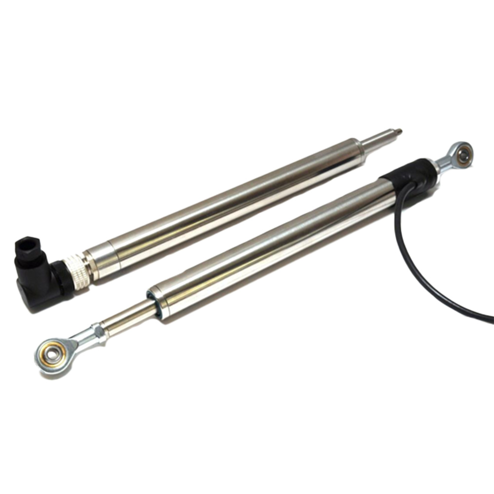
The LS17 Slimline Linear Position Sensor has been specifically designed for industrial and scientific applications that require a narrow bodied position sensor. Exquisitely engineered, the 19mm diameter body of the sensor is constructed from stainless steel and when combined with the non-wearing inductive technology, will deliver dependable performance for many years.
The non-wearing inductive technology used in the LS17 is a major advance in displacement sensor design. This transducer has the simplicity of a potentiometer with the life of an LVDT. The LS17 sensor outputs a stable DC analogue signal by using simple inductive coils in conjunction with advanced ASIC control technology. As there is no contact between moving electrical components, reliability is high and wear is eliminated for an exceptionally long life. It also overcomes the drawbacks of LVDT technology that typically include; bulky coils, poor length-to-stroke ratios, separate signal conditioning requirements and the need for special magnetic materials.
The LS17 provides a linear output proportional to travel. Each unit is supplied with the output calibrated to the travel required by the customer, any stroke from 0-5mm to 0-350mm can be specified during the order process. The default accuracy of the LS17 is 0.25% FSO, however if you would like a greater accuracy of 0.1% FSO then this can be specified during the ordering process too.
The sensor is very robust, the body and push rod being made of stainless steel for long service life and environmental resistance. It is particularly suitable for OEMs seeking good sensor performance for arduous applications such as industrial machinery where cost and reliability is important.
Overall performance, repeatability and stability are outstanding over a wide temperature range. The sensor is easy to install with mounting options including M5 rod eye bearings and body clamps. The push rod by default is supplied, free or captive, with female M5x0.8×10 long thread. Alternatively, M5 rod eye, dome end or magnetic tip options are available too. Captive push rods can be sprung loaded, in either direction, on sensors up to 350mm of travel. The LS17 also offers a wide range of mechanical and electrical options and is IP67 rated. The ability for the LS17 to remain unaffected by external electromagnetic interference is assured by the built in EMC protection that conforms to EN 61000-6-2 and EN 61000-6-3 standards.
Common applications for the Applied Measurements LS17 position sensor include geotechnical testing, R&D, aerospace, civil engineering and automotive.
Applied Measurements can supply a wide variety of instrumentation to complement your LS17 position sensor, such as wireless transmitters and receivers, digital displays and amplifiers.
Technical Specifications
| Dimensions | |
| Body Diameter | 19mm |
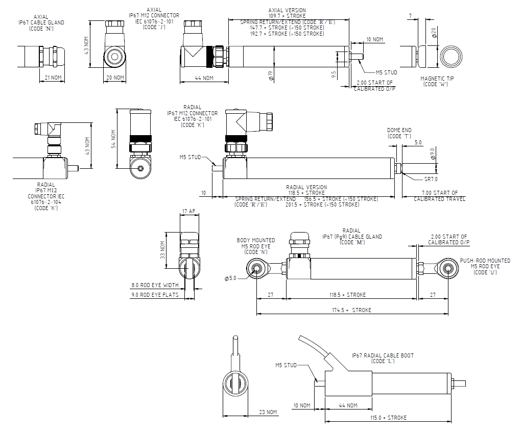
| Body Length (Axial version) | calibrated travel + 109.7mm |
| Sprung <150mm stroke | calibrated travel + 147.7mm |
| Sprung ≥150mm stroke | calibrated travel + 192.7mm |
| Body Length (Radial version) | calibrated travel + 118.5mm |
| Sprung <150mm stroke | calibrated travel + 156.5mm |
| Sprung ≥150mm stroke | calibrated travel + 201.5mm |
| Push Rod Extension | calibrated travel + 2mm, OD 9.5mm |
| Non-Linearity | ≤±0.25%/FSO @ 20°C |
| Temperature Coefficients | |
| Gain | <±0.01%/°C |
| Offset | <±0.01%FS/°C |
| Frequency Response (-3db) | |
| Voltage and 4-20mA (3-wire) Outputs | >10kHz |
| 4-20mA (2-wire loop-powered) Output | >300Hz |
| Resolution | Infinite |
| Noise | <0.02%/FSO |
| Operating | -20°C to +85°C (standard) -40°C to +125°C (optional) |
| Storage | -20°C to +85°C |
| Sealing | IP68 to 10bar / IP69K |
| EMC Performance | EN 61000-6-2, EN 61000-6-3 |
| Vibration | IEC 68-2-6: 10g |
| Shock | IEC 68-2-29: 40g |
| MTBF | 350,000 hrs 40°C Gf |
Product Dimensions
Electrical Output Options
| Output Option Code | Output Type | Supply Voltages | Load resistance |
|---|---|---|---|
| A | 0.5 - 4.5Vdc (ratiometric with supply) | +5Vdc (4.5 - 5.5V) | ≥5kΩ |
| C | 0.5-9.5Vdc | +24Vdc nom. (13 - 28V) | ≥5kΩ |
| G | 0.5-4.5Vdc | +24Vdc nom. (9 - 28V) | ≥5kΩ |
| H | 4-20mA (3-wire source) | +24Vdc nom. (13 - 28V) | ≈ 0 - 300Ω max. ~ 1.2 to 6V across 300Ω |
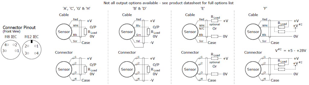
Wiring Details
Mechanical Mounting
Depending on options; Body can be mounted by M5x0.8 male thread, rod eye or by clamping the sensor body – body clamps are available, if not already ordered. Target by M5x0.8 male thread, rod eye or magnetic tip. It is assumed that the sensor and target mounting points share a common earth.
Output Characteristic
Target is extended 2mm from end of body at start of normal travel. The output increases as the target extends from the sensor body, the calibrated stroke is between 5mm and 350mm.
Connector Warning
The M12x1 connector may be rotated for purposes of convenient orientation of the connector and cable, however rotating the connector more than one complete revolution is not recommended. Repeated rotation of the connector will damage the internal wiring!
| WARNINGS | |
| A | Not protected – the sensor is NOT protected against either reverse polarity or over-voltage. The risk of damage should be minimal where the supply current is limited to less than 50mA. |
| C & G | Supply leads diode protected. Output must not be taken outside 0 to 12V. |
| H | Supply and output lead diode protected. Do take output negative of 0 volts. |
V23.09.2021
Ordering Codes & Options
| Example code | LS17 | A | - | 350 | - | L | A | - | 0 | 0 | U | N | - | Z | - | 000 | |
|---|---|---|---|---|---|---|---|---|---|---|---|---|---|---|---|---|---|
| Product Family | |||||||||||||||||
| LS17 | LS17 | ||||||||||||||||
| Electrical Output | |||||||||||||||||
| 0.5-4.5Vdc (ratiometric with supply) | A | ||||||||||||||||
| 0.5-9.5Vdc | C | ||||||||||||||||
| 0.5-4.5Vdc | G | ||||||||||||||||
| 4-20mA (3-wire source) | H | ||||||||||||||||
| - | |||||||||||||||||
| Displacement | |||||||||||||||||
| From 5mm to 350mm, in 1mm steps | XXX | ||||||||||||||||
| - | |||||||||||||||||
| Electrical Connection | |||||||||||||||||
| Radial Cable Boot (IP67) | L | ||||||||||||||||
| Radial Cable Gland (IP67) | M | ||||||||||||||||
| Axial Cable Gland (IP67) | N | ||||||||||||||||
| Radial Connector, 4-pin M12 (IP67) | K | ||||||||||||||||
| Axial Connector, 4-pin M12 (IP67) | J | ||||||||||||||||
| Cable Length | |||||||||||||||||
| No cable | 0 | ||||||||||||||||
| 1m | A | ||||||||||||||||
| 2m | B | ||||||||||||||||
| 3m | C | ||||||||||||||||
| 5m | D | ||||||||||||||||
| 10m | E | ||||||||||||||||
| 15m | F | ||||||||||||||||
| 20m | G | ||||||||||||||||
| - | |||||||||||||||||
| Body Fittings | |||||||||||||||||
| None (standard) | 0 | ||||||||||||||||
| M5 Rod-End Bearing (with radial electrical connection only) | N | ||||||||||||||||
| Push Rod | |||||||||||||||||
| Not Sprung (standard) | 0 | ||||||||||||||||
| Spring Extend | E | ||||||||||||||||
| Spring Retract | R | ||||||||||||||||
| Push Rod Fittings | |||||||||||||||||
| M5 Male Thread (standard) | 0 | ||||||||||||||||
| Dome End (available with spring extend option 'E' only) | T | ||||||||||||||||
| M5 Rod-End Bearing | U | ||||||||||||||||
| Magnetic Tip | W | ||||||||||||||||
| Push Rod | |||||||||||||||||
| Captive/Retained (standard) | N | ||||||||||||||||
| Non-Captive (can depart body - not available on sprung options) | V | ||||||||||||||||
| - | |||||||||||||||||
| Output Polarity Calibration | |||||||||||||||||
| Standard | 0 | ||||||||||||||||
| Reversed | R | ||||||||||||||||
| Accuracy @ 20ºC | |||||||||||||||||
| Standard Non-Linearity | 0 | ||||||||||||||||
| Improved Non-Linearity: ≤±0.1%/FSO (0-10mm ranges and higher only) | Z | ||||||||||||||||
| - | |||||||||||||||||
| Special Code | |||||||||||||||||
| No Special Requirements | 000 | ||||||||||||||||
| Technical Sales will provide specials codes as required | XXX |
ACCESSORIES
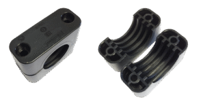
The black polyamide 19mm body clamp fits the LS17 perfectly and is an essential accessory if you need to mechanically grip the body of the displacement sensor and secure both to an external structure e.g. test rig. The BP352 is designed to be secured by 2 x M6 Fixings (not supplied).

Due to our policy on ongoing development, dimensions and specifications may change without notice.
Downloads
CAD Model Files
Our 3D models are provided in STEP format and can be viewed using FreeCAD. Other formats can be provided on request.
The .zip file below contains a separate model for each product variant.
Why Applied Measurements?
- Suppliers of top quality strain gauge sensors and transducers to every corner of industry - UK and worldwide
- Over 100 years of expert transducer knowledge
- Our high quality products all come with a 3 year warranty
Related Products
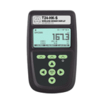
 IP67-Rated Wireless Roaming 12 Channel handheld Receiver With Illuminated Display | T24-HK-SFrom £629
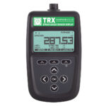
- Strain Gauge Sensor Display | Digital Indicator | TRXTEDS EnabledFrom £329Buy Online
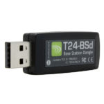
- Wireless USB Dongle Receiver | T24-BSdFrom £248
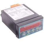
- Load Cell Digital Indicator | High Accuracy | Intuitive4-LHighly configurable, modular constructionFrom £364Buy Online
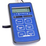
- Handheld Load Cell Indicator | Digital Display | TR150From £495Buy Online
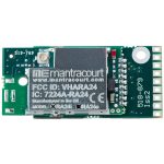
- Fast Wireless Strain Gauge PCB Transmitter with 2000Hz resolution | T24-SAfFrom £498
- Wireless Strain Gauge PCB Transmitter with 200Hz resolution | T24-SAFrom £360
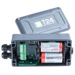
- Industrial IP67-rated, D-battery Enclosure for PCB transmitters | T24-ACMFrom £580
Popular Products
- Platform Load Cell | Single Point Load Cell | 0-250g to 0-40kg | OBUG0-250g to 0-40kgFrom £128Buy Online
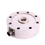
- Pancake Load Cell | Low Profile Force Sensor | DSCC0-5kN up to 0-1000kNFrom £651Buy Online
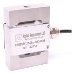
- Universal Load Cell | Universal S-Beam Force Sensor | DBBSM0-1kg up to 0-30,000kgFrom £269Buy Online
- Handheld Load Cell Indicator | Digital Display | TR150From £495Buy Online
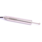
- Strain Gauge Displacement Sensor | Linear Position Sensor | AML/SGD0-5mm to 0-100mmFrom £429Buy Online