Applied Measurements torque sensors deliver high precision and top performance. We offer both standard and customised torque transducers.
What’s more, Applied Measurements offer alternative connections through couplings and customised solutions for your specific applications.
Plus, Applied Measurements are an approved UK distributor of the ETH Messtechnik torque sensors manufactured in Germany.
Torque Transducers & Torque Sensors Explained
Product Links
Filters
Availability
Shape/Type
Torque Capacity
Environment
Mechanical
Speed
For Use With
Type
Accuracy
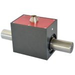
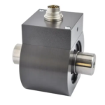
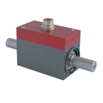
 Brushless Rotary Square Drive Torque Sensor | DRFN0-1Nm to 0-5000NmFrom £3,147Buy Online
- Dual-Range Rotary Torque Sensor | DRDL0-0.5Nm to 0-1500NmFrom £5,836Buy Online
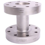
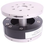
- Flange type Static/Reaction Torque Transducer | DTD-F0-10Nm to 0-50kNmFrom £1,263
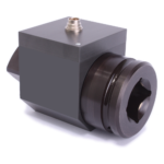
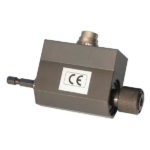
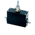
- Hexagonal Drive Rotary Torque Sensor | DRFS0-1Nm to 0-20NmFrom £3,147
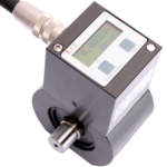
- Low Cost Rotary Torque Sensor with Display | DRBK-A0-0.5Nm to 0-1000NmFrom £3,014Buy Online
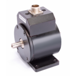
- Low Cost Rotary Torque Sensor | DRBK0-0.5Nm to 0-1000NmFrom £1,939Buy Online
- Miniature Rotary Torque Transducer | YDSA0-0.2Nm to 0-50NmFrom £2,547Buy Online
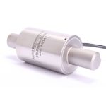
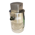
- Miniature Shaft Torque Sensor | Static/Reaction Torque | YDNS0-0.2Nm to 0-1000NmFrom £2,122Buy Online
- Parallel Shaft Reaction Torque Transducer | DTD-P0-10Nm to 0-10kNmFrom £911
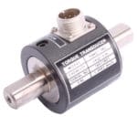
- Shaft type Brushless Rotary Torque Sensor | DRVL0-0.02Nm to 0-20kNmFrom £3,230Buy Online
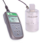
- Square Drive Static Torque Transducer | DTD-S0-10Nm to 0-50kNmFrom £911
- Torque Measurement System | Torque Testing System0-10Nm to 0-20kNmFrom £1,410
- Waterproof Rotary Torque Sensor | DRWPL0-0.1Nm to 0-1500NmFrom £4,176Buy Online
- Wireless Rotary Torque Sensor | DTDR-F0-10Nm to 0-50,000NmFrom £4,981
Torque Sensors Explained
What is Torque?
Torque is a twisting or turning force about an axis, that can be applied in a clockwise or counter-clockwise direction. A good example of this is a vehicle steering mechanism; to turn a corner the driver applies a force to the steering wheel which applies torque directly to the steering column. This torque is generated by a combination of the force from the driver’s hands and distance the hands are from the centre of the wheel.
Torque is a function of force and length (known as the moment or moment arm), this is shown below in our simple ‘seesaw’ diagram. The seesaw is balanced even though the forces applied to each side are different, this is because the torque at the middle point is the same. The calculations are as follows:
Left Side = 100N force x 1 metre = 100Nm of torque
Right Side = 300N force x 1/3 metre = 100Nm of torque
The most common metric engineering units for torque is the Newton metre (Nm), whilst the most common imperial engineering units is foot pounds (ft.lb).
A torque measuring device is needed to measure torque. Torque sensors are torque-measuring devices. Read the below Torque Sensor Measurement Principle to learn how these torque measuring devices work.
Torque Sensor Measurement Principle
The most common torque sensor measurement principle uses bonded strain gauge technology, where the strain gauges are bonded to a suitably designed shaft. Torque transducers with a circular shaft and with strain gauges applied at 45deg is a design that has been around for many years. However, the design and configuration of the device will be dictated by the application and the shaft may well be solid or hollow and the cross-section might differ with either a cruciform, square or the other custom design, in order to gain the maximum signal output available from the measurement.
When torsion is applied to the shaft causing it to twist, shear stresses are induced. These are measured by bonding the strain gauges at 45° to the horizontal torque axis. As the shear stress induced in the shaft is the same throughout its length, the strain gauges can be bonded at any point along its length. However, it is normal practice to place them in the centre, as far as possible from spurious stress that can be induced at the mechanical interfaces.
Getting an Electrical Signal from the Torque Transducer
Typically four strain gauges are bonded and connected into a Wheatstone bridge configuration with temperature compensation components included within the bridge circuitry. With an excitation voltage applied to the bridge and torque induced into the shaft, an electrical output linearly proportionate to that torque will result.
For the strain gauged shaft to become a useful measuring instrument (torque sensor) it is necessary to calibrate it with a known reference standard. This can be either weight applied to the end of a cantilever arm of known length, or in line with a reference standard torque transducer.
The completed Wheatstone Bridge requires a stable DC supply to excite the circuit. This is usually 5Vdc or 10Vdc but can be any value from 1Vdc up to 18Vdc.
Torque Sensors and Torque Sensor Instrumentation
These low-level millivolt signals are compatible with a vast range of bespoke strain gauge sensors such as load cells and pressure transducers and their associated instrumentation. These instruments include digital displays, analogue and digital amplifiers. Typical analogue amplifiers will generate a higher level voltage (0-5Vdc, 0-10Vdc) or current (0-20mA, 4-20mA) for additional processing.
Typically digital amplifiers also provide RS232 or RS485 output using either industry standards or protocols specific to an industry such as MODbus. In many cases the signal conditioning is built into the device, giving a direct analogue or digital output for further processing.
One of the latest developments to be incorporated into torque sensors is radio telemetry operating in the 2.4GHz frequency band. Operating with very low current consumption enables the use of small batteries on a power source. This latest technology has led to the design of contactless rotary torque transducers.
A further benefit of radio telemetry torque sensors is their low cost (up to 50%) compared with equivalent slip-ring or brushless types.
Selection of an appropriate device will be based on the following amongst other factors, all of which will impact on the accuracy and cost of the measurement, these include:
- Speed of rotation
- The environment in which the measurement is taking place
- The mechanical connection
- Test duration
- Information required for the measurement being taken
Static / Reaction Torque (less than 1 revolution) vs. Rotary Torque (greater than 1 revolution)
Torque measurements can be either Static (also known as Reaction) or Rotary. A static or reaction torque measurement involves little or no rotation of the item being measured, such as during torque spanner testing. A rotary torque measurement would, as the name suggests, be subject to continuous rotation. This rotation could be constant, as you find in a system measuring the torque on a stirrer in a mixing vessel or periodical as you would find when measuring the torque produced by an electric screwdriver.
Dynamic Torque
A dynamic torque meanwhile is one that is subject to variation or change, for instance, the torque on the motor drive shaft of an electric hover mower would be subject to dynamic torque, firstly as you turn on the power to make the blade spin up, and thereafter as you move the mower around your lawn between areas of varying grass density, or from cut to uncut grass.
When selecting a torque measuring device to measure dynamic torque, it is important to ensure that Is has a sufficiently wide frequency response bandwidth so that the electrical output will react fast enough to capture the changes (peaks or troughs) as they occur, rather than smoothing or filtering them out.
Power & Signal Transmission in Rotary Torque Sensors
Slip Ring
The first rotating strain gauge torque transducer employed slip rings to make the electrical connections from the casing to the rotating shaft. Because the slip rings carry only millivolt signals from the strain gauges, the materials for both the slip rings and the brushes must be very carefully selected. The normal procedure is to use coin silver for the slip rings and silver graphite for the brush gear.
The conductive rings rotate with the sensor and use a series of sprung brushes to contact the rings and transmit the electrical signal. Slip rings are relatively straightforward with only minor drawbacks in that the brushes and to a lesser extent, the rings, do wear and as such have a finite life. Because of this, they don’t lend themselves to long-term tests, very high speed or to applications where access to the sensor for servicing is limited.
At low speed the electrical connection between the rings and brushes are relatively noise-free, however, at higher speeds electrical noise will eventually degrade their performance. The maximum speed (rpm) for a slip ring is determined by the surface speed at the interface between the brush and the ring. As a result, the maximum operating speed will be lower for larger, or higher torque capacity sensors because the larger slip rings will, therefore, have a higher surface speed at a given rpm. Typical maximum rpm will be in the range of 5,000 rpm for a medium-capacity torque sensor. For very low capacity measurements, the brush ring interface can be a source of ‘drag torque’ that can be a problem for the driving torque to overcome.
Rotary Transformer (Inductive Loop)
For higher speed (rpm) torque measurement applications the rotary transformer system might be used. The rotary transformer system consists of two coils, one static coil that is attached to the transducer’s housing and one rotating coil that is attached to the transducer shaft. This offers the distinct advantage of there being no contact between the rotor and stator and incorporates both transmission of power to and signal back from the rotating strain gauge bridge circuit. Rotary transformer-type torque sensors offer typical inaccuracies of ±0.2% and are capable of speeds up to 50,000rpm.
The rotary transformer system is versatile enough for use in special torque transducers and those where space is limited. However as this design incorporates bearings, the maximum rpm is more than the slip-ring design but limited by the maximum specified performance of the bearing. The system can also be susceptible to noise and errors, which are induced by the alignment of the transformer’s primary-to-secondary coils. Because of the special requirements imposed by the rotary transformers, specialised signal conditioning is also required in order to produce a signal acceptable for most data acquisition systems.
Wireless Radio Telemetry (Battery Powered, 2.4GHz)
Following the advent of modern low-power wireless telemetry acquisition and transmission electronics, it has become possible to manufacture battery-powered torque sensors that offer a sufficiently long period of operation between charges to make them viable in a wide range of industrial and research applications.
The avoidance of rotor and stator coils means that installing wireless torque sensors is a simplified process over other types as there is no cabling provision or coil alignment to consider, it also means that the measurement signal can be transferred over considerable distances (up to 120m) easily.
The data stream provided by the wireless telemetry system is broadcast and so can be read by multiple receiver units with different functions such as digital displays, analogue outputs and PC-based USB acquisition making multi-featured systems quick and easy to set up.
Mechanical Couplings
A coupling is a device used to connect two shafts together at their ends for the purpose of transmitting power and protecting the connected equipment from the damaging effects of misalignment, vibration and shock overload. The primary purpose of couplings is to join two pieces of rotating equipment while permitting some degree of misalignment or end movement or both. By careful selection, installation and maintenance of couplings, substantial savings can be made in reduced maintenance costs and downtime.
The torque transducer will accommodate only a small amount of misalignment, but ideally, no misalignment should exist between the input and output shafts. Severe misalignment will lead to premature bearing failure due to the repeated stresses developed in the contact areas between the bearings and the raceway, even if the coupling is properly mounted and maintained. In correctly aligned shafts, the bearings will be subjected to loads less than the established rated loads for the bearings in which case will result in extended bearing life.
Popular types used are disk (or plate) / bellows / diaphragm / elastomer / grid / gear and many other proprietary names given by different suppliers. The selection of a suitable coupling type is based on speed, torque rating, environment, access, degree of misalignment and the service life required.
Torque Measurement Summary
To measure torque effectively it is important to understand the factors involved in the creation of the torque as well as those that may alter the torque measurement, as these will impact the selection of an appropriate transducer. Criteria such as nominal torque rating, speed, available space to mount the sensor, duration of measurement and the environment within which the measurement is taking place are amongst the most significant criteria that will dictate torque sensor selection.
When measuring dynamic torque, the location of the measurement is vital to ensure that the true torque is measured and false measurements are avoided, caused by either adjoining components in the drive train or those that dampen the torque measurement system, including the measurement system itself.
Usually, the physical and environmental factors present will pinpoint the selection of appropriate equipment. The selection of the correct transducer rating, transmission system and mechanical connection will ensure the measurement solution is no more expensive than it needs to be and maximum long-term accuracy and reliability will be achieved.
Case Studies
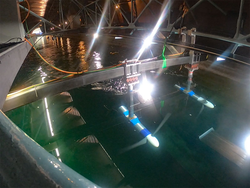
Applied Measurements Promise Precise Thrust & Torque Results in Tidal Turbine Testing
Read how our dual axis force and torque sensors was used in tidal testing by the University of Oxford. They aimed to understand how the spacing between tidal turbines and different control strategies affects the performance of tidal turbines.
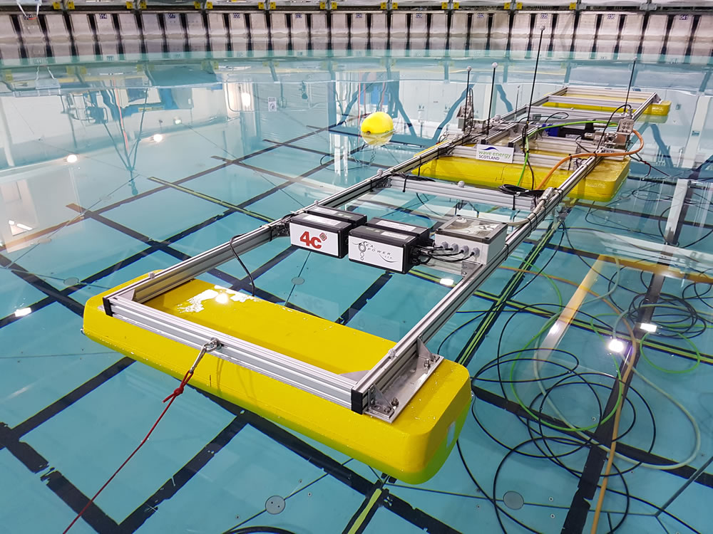
Real Life: Power Take-Off Torque Monitoring – Accurate, Fast and Simple!
Read the real life case study of power take-off torque monitoring on the Wave Energy Converter The SeaPower Platform. See how our complete torque measuring system enabled engineers to accurately monitor the torque applied by the Wave Energy Converter as it responded to waves in the test tank with accurate, fast and reliable results.
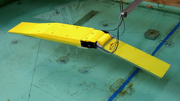
Incredible Miniature Reaction Torque Sensor Helps Create Ocean Energy
The YDNS miniature reaction torque sensor's compact size and in-line direct drive measurement capability meant it could easily be housed within the waterproof enclosure of the 1/50th scale wave energy converter.
Interested in our torque measurement products? Let us call you…
Why Choose Applied Measurements?
- Applied Measurements are suppliers of top quality strain gauge sensors and transducers to every corner of industry – UK and worldwide
- We have over 100 years of expert transducer knowledge
- Applied Measurements high-quality products all come with a 3 year warranty