At a Glance
- Capacities: 0-10Nm to 0-50kNm
- mV/V Strain Gauge Bridge Output
- Environmental Protection: IP65
- Accuracy: <±0.1%/Rated Capacity
- Custom Capacities to 200kNm+
- Ideal for Bolting Between Machinery to Measure Direct Torque
- IP65 Protected From Low Pressure Water Jets
- IP68 Submersible Versions Available
- Fast and Simple Installation
- Fully Customised Versions to Suit Your Exact Application
Description
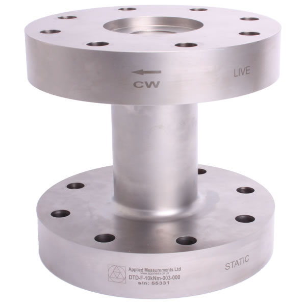
The DTD-F series of static / reaction torque transducers have end flanges for bolting between machinery where a direct drive is required. Applications including the testing of automotive drives, aircraft actuator and industrial robots.
The DTD-F flange static torque transducer is constructed from Stainless Steel making it highly robust, durable and corrosion-resistant, and therefore ideal for a multitude of demanding applications.
Installation and setup is made fast and simpler with its integral, robust connector.
The design of the DTD-F lends itself readily to customisation, allowing us to offer custom flange sizes and fixing configurations, as well as versions with sealing to IP68 for applications where operating conditions are particularly harsh or involve total submersion.
If you need a torque transducer without a flange end, please see our range of alternative static torque transducers.
Technical Specifications
| Rated Capacity (RC) | Nm | 0-10, 0-20, 0-50, 0-100, 0-200, 0-300, 0-500, 0-1000, 0-2k, 0-3k, 0-5k, 0-10k, 0-20k, 0-30k, 0-50k |
| Operating Modes | Clockwise (CW)/Counter-Clockwise (CCW) / Clockwise (CW) & Counter-Clockwise (CCW) | |
| Sensitivity (RO) | mV/V | 10Nm = 0.6 / 20Nm = 0.7 / 50Nm to 50kNm = 1 to 1.5 typical |
| Zero Balance/Offset | ±%/Rated Output | <1 |
| Output Symmetry (CW vs. CCW) | ±%/Rated Output | <0.25 typical |
| Non-Linearity | ±%/Rated Output (BFSL) | <0.1 (<0.05 typical) |
| Hysteresis | ±%/Full Scale Output | <0.1 (<0.05 typical) |
| Repeatability | ±%/Full Scale Output | <0.02 |
| Temperature Effect on Zero | ±Full Scale Output/ºC | <0.010 |
| Temperature Effect on Output | ±/Reading/ºC | <0.010 |
| Bridge Resistance | Ohms | 700 nominal |
| Insulation Resistance | Megaohms | >5000 @ 50Vdc |
| Excitation Voltage | Volts AC or DC | 10 recommended (2-15 acceptable) |
| Operating Temperature Range | ̊C | 0 to +80 |
| Compensated Temperature Range | ̊C | +20 to +60 |
| Storage Temperature Range | ̊C | 0 to +80 |
| Safe Overload | % of Rated Capacity | 150 |
| Ultimate Overload | % of Rated Capacity | 300 |
| IP Rating (Environmental Protection) | IP65 | |
| Weight | See dimensions table | |
| Fatigue Rating | 20 million fully-reversed cycles | |
| Cable Length (as standard) | metres | 3 |
| Cable Type | 10Nm to 10kNm: M8 Binder connector with mating 3 metre cable assembly 20kNm to 50kNm: M12 Binder connector with mating 3 metre cable assembly |
|
| Construction | 17-4PH stainless steel + 303 stainless steel | |
| Resolution | 1 part in 250,000 (with appropriate instrumentation) |
Product Dimensions
| Capacity (Nm) | A | ØB | ØC | D | E | ØF | G | Weight kg (approximate) |
|---|---|---|---|---|---|---|---|---|
| 0-10, 0-20, 0-50, 0-100 | 76 | 100 | 38.1 | 13 | 2 | 82.5 | 8.2 | 1.4 |
| 0-200, 0-500 | 76 | 100 | 38.1 | 13 | 3 | 82.5 | 8.2 | 1.4 |
| 0-1000, 0-2000 | 90 | 125 | 50.1 | 19 | 6 | 108 | 10.2 | 3.1 |
| 0-3000 | 120 | 150 | 50.1 | 35 | 6 | 108 | 16.3 | 8.7 |
| 0-5000 | 120 | 202 | 80.1 | 38 | 8 | 165 | 16.3 | 16.9 |
| 0-10k | 190 | 202 | 80.1 | 38 | 8 | 165 | 16.3 | 17.2 |
| 0-20k, 0-30k, 0-50k | 180 | 278 | 110.1 | 50 | 4 | 235 | 24.5 | 56 |
All dimensions are in mm.
Wiring Details
| Wire | Designation |
|---|---|
| Red | +ve excitation |
| Blue | -ve excitation |
| Green | +ve signal (clockwise) |
| Yellow | -ve signal |
| Screen | To ground - not connected to sensor body |
Ordering Codes & Options
| Core Product | Capacity (inc Engineering Units) | Cable Length (m) | Specials Code | Result |
|---|---|---|---|---|
| DTD-F | 10Nm | 003 | 000 | DTD-F-10Nm-003-000 |
| DTD-F | 20Nm | 003 | 000 | DTD-F-20Nm-003-000 |
| DTD-F | 50Nm | 003 | 000 | DTD-F-50Nm-003-000 |
| DTD-F | 100Nm | 003 | 000 | DTD-F-100Nm-003-000 |
| DTD-F | 200Nm | 003 | 000 | DTD-F-200Nm-003-000 |
| DTD-F | 300Nm | 003 | 000 | DTD-F-300Nm-003-000 |
| DTD-F | 500Nm | 003 | 000 | DTD-F-500Nm-003-000 |
| DTD-F | 1000Nm | 003 | 000 | DTD-F-1000Nm-003-000 |
| DTD-F | 2000Nm | 003 | 000 | DTD-F-2000Nm-003-000 |
| DTD-F | 5000Nm | 003 | 000 | DTD-F-5000Nm-003-000 |
| DTD-F | 10,000Nm | 003 | 000 | DTD-F-10kNm-003-000 |
| DTD-F | 20,000Nm | 003 | 000 | DTD-F-20kNm-003-000 |
| DTD-F | 30,000Nm | 003 | 000 | DTD-F-30kNm-003-000 |
| DTD-F | 50,000Nm | 003 | 000 | DTD-F-50kNm-003-000 |
Due to our policy on ongoing development, dimensions and specifications may change without notice.
Downloads
CAD Model Files
Our 3D models are provided in STEP format and can be viewed using FreeCAD. Other formats can be provided on request.
The .zip file below contains a separate model for each product variant.
Why Applied Measurements?
- Suppliers of top quality strain gauge sensors and transducers to every corner of industry - UK and worldwide
- Over 100 years of expert transducer knowledge
- Our high quality products all come with a 3 year warranty
Related Products
 Load Cell Digital Indicator | High Accuracy | Intuitive4-LHighly configurable, modular constructionFrom £364Buy Online
- Large Digit Load Cell DisplayFrom £503
- Handheld Load Cell Indicator | Digital Display | TR150From £495Buy Online
- T24 Wireless Telemetry
- Miniature Load Cell Amplifier | In-Cell Amplifier | ICAFrom £85Buy Online
- Load Cell Amplifier | Load Cell Signal Conditioner | SGAInputs from 0.06mV/VFrom £235Buy Online
- USB Load Cell Interface | DSCUSB100 Readings/Second max.From £335Buy Online

Popular Products
- Platform Load Cell | Single Point Load Cell | 0-250g to 0-40kg | OBUG0-250g to 0-40kgFrom £128Buy Online
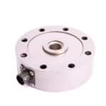
- Pancake Load Cell | Low Profile Force Sensor | DSCC0-5kN up to 0-1000kNFrom £651Buy Online
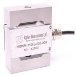
- Universal Load Cell | Universal S-Beam Force Sensor | DBBSM0-1kg up to 0-30,000kgFrom £269Buy Online
- Handheld Load Cell Indicator | Digital Display | TR150From £495Buy Online
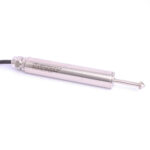
- Strain Gauge Displacement Sensor | Linear Position Sensor | AML/SGD0-5mm to 0-100mmFrom £429Buy Online