


At a Glance
- Ranges: 0-500mbar up to 0-700bar
- Output: I²C
- Environmental Protection: IP65 (IP67 optional)
- Accuracy: <±0.25%/FS (<±0.1% optional)
- Stainless Steel Construction
- UK-Made
- UK-Manufactured, Short Lead Times
- I²C Protocol for Bi-Directional Data Transfer
- IP65 Splash-Proof for Industrial Applications
- 2 Week Delivery!
- High-Volume Production Available
- Customised & OEM Versions
Description
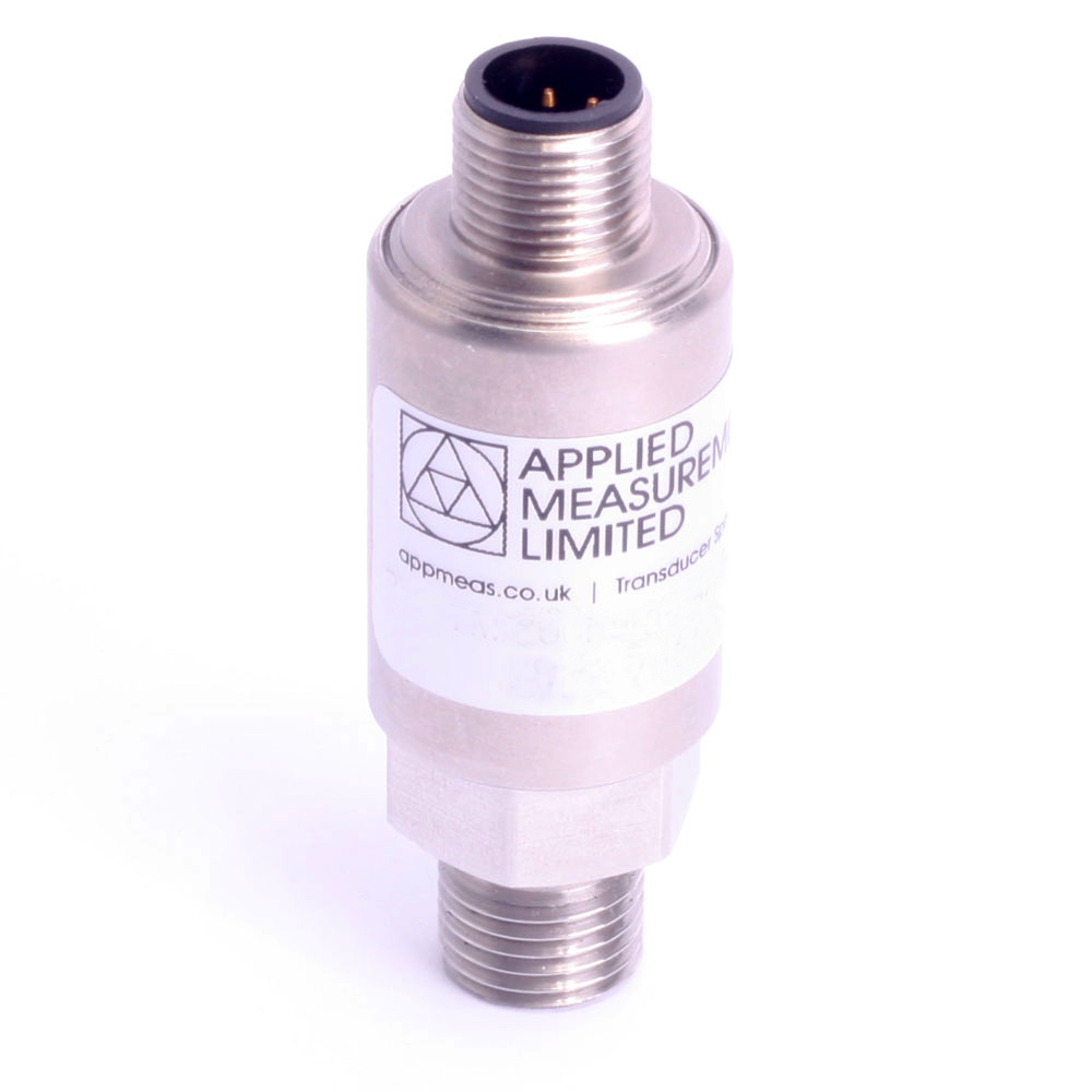
Applied Measurements I²C pressure sensor Pa6DC uses an I²C (Inter-Integrated Circuit) protocol to communicate with the controller. The I²C output is ideal for OEM, machine feedback systems, control systems and automation applications.
I²C Pressure Transducer Prices Start From:
- 1+ = £120.00
- 10+ = £115.00
- 25+ = £108.00
- 50+ = £102.00
- 100+ = £97.00
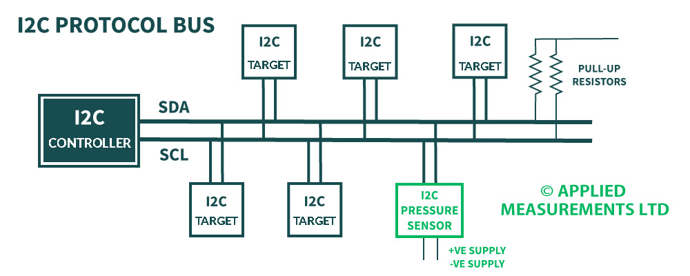
The benefit of using our I²C pressure transducer with an I²C interface is that it can be supported along with many I²C devices on the same circuit. I²C protocol allows a maximum of 127 target devices on the bus. This I²C pressure sensor is designed to work as a target on an I²C protocol bus.
As with most I²C devices, the I²C pressure sensor uses only 2 wires to transmit data between the devices on the system (2 further wires are required from the pressure sensor for the +ve and -ve supply, see I²C protocol diagram below).
The pressure sensor’s housing is constructed from 303 stainless steel (alternative materials including 316 stainless steel and PVDF are available) and utilises a ceramic sensing diaphragm (96% aluminium oxide Al2O3), a Viton O-ring and a G¼ inch male process connection as standard, giving the sensor an IP65 splashproof protection rating.
Thanks to its IP65 sealing, it can be used for the measurement of gas and liquid pressure in many I²C industrial applications.
We can easily accommodate any requirement from one-off to bulk orders for many thousands of sensors, all within our in-house, UK production facility.
Alternate casing and construction materials, O-rings and process connections can all be offered, including G¼” female and ¼” NPT male connectors. Should you require a pressure sensor tailored to your specific pressure measurement application, we can design and manufacture fully customised sensors for you – please contact our friendly sales team to discuss your requirements in detail.
How I²C Protocol Works
I²C communication protocol uses 2 wires to transmit information between the controller and the target on an I²C bus, the SDA and the SCL. The Serial Data Line (SDA) carries the data bi-directionally between the controller and the target device. The Serial Clock Line carries the clock signal ensuring the target and the controller’s clock are synchronised. The Clock signal is always controlled by the controller.
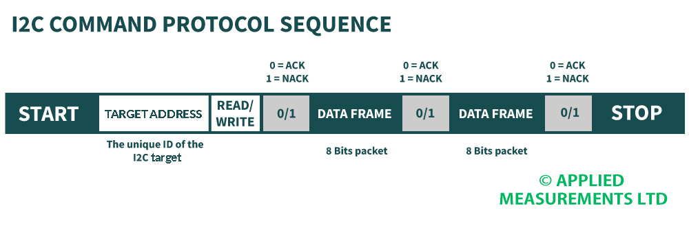
Each I²C device connected to the bus has a unique address. This is used by the controller to differentiate between the various target devices on the I²C bus. The I²C pressure sensor works as a target on the bus.
Benefits of an I²C Communication Bus
- Easy to add on, remove and modify the design by easily clipping on and clipping off the I²C devices.
- Easy to install as the I²C communications protocol is already embedded on the chip inside the sensor.
- Simple 2-wire data transfer.
- Easy fault finding with the unique address of every I²C-connected device.
- Low current consumption.
Technical Specifications
| Input Pressure Range | |||||||||||||
|---|---|---|---|---|---|---|---|---|---|---|---|---|---|
| Nominal Pressure Range | Bar (gauge, absolute or sealed gauge | 0-0.5 | 0-1 | 0-2 | 0-5 | 0-10 | 0-20 | 0-50 | 0-100 | 0-200 | 0-400 | 0-600 | 0-700 |
| Compound Ranges | Bar | -0.5…0 * | -1…0 * | -1…+2 * | -1…+5 | -1…+9 | -1...+19 | -1...+29 | - | - | - | - | - |
| Permissible Overpressure | Bar | 1 | 2 | 4 | 10 | 15 | 35 | 100 | 150 | 350 | 500 | 800 | 900 |
| Burst Pressure | Bar | 2 | 3 | 6 | 15 | 25 | 65 | 120 | 200 | 500 | 650 | 950 | 950 |
| *<±0.1% / FS (BFSL) accuracy not possible in this range | |||||||||||||
| Output Signal & Supply Voltage | Wiring System | Output | Supply Voltage | Input Current (idle) |
|---|---|---|---|---|
| Pa6DC | 4-wire | I²C | 2.7-5.5Vdc | <3mA |
| Performance | ||
|---|---|---|
| Accuracy (Non-Linearity, Hysteresis & Repeatability) | ±%/Rated Output (BFSL) | <±0.25 <±0.1 optional |
| Zero Balance | ±% of Rated Output | <1.0 |
| Setting Errors (offsets) | Zero & Full Scale, <±0.5% / FS | |
| Influence Effects | Supply Effects | <0.005 % FS / 1V |
| Response Time (10% - 90%) | ms | 1 minimum, dependent on device configuration |
| Start-Up Time | ms | 2 |
| Wake-Up Time (from Sleep Mode) | µs | 10 |
| Internal I²C Pull-Up Resistors | kΩ | 4.7 |
| Permissible Temperatures & Thermal Effects | ||
| Media Temperature (Note: subject to 'O' ring seal, see below) | ˚C | -40 to +135 |
| Ambient Temperature | ˚C | -20 to +85 |
| Storage Temperature | ˚C | -20 to +85 |
| Compensated Temperature Range | ˚C | +20 to +80 |
| Thermal Zero Shift (TZS) | % / FS / ˚C | <±0.04 (standard) <±0.02 (option) <±0.01 (option) |
| Thermal Span Shift (TSS) | % output / ˚C | <±0.015 typical |
| Electrical Protection | ||
| Reverse Polarity Protection | No damage but also no function | |
| Electromagnetic Compatibility | CE Compliant | |
| Insulation Resistance | Megohms Ω at 50V dc | >500 |
| Mechanical Stability | ||
| Shock | 100 g / 11 ms | |
| Vibration | 10 g RMS (20 ... 2000 Hz) | |
| Materials | ||
| Housing & Process Connection | 303 Stainless Steel 316L Stainless Steel (optional) |
|
| ‘O’ Ring Seals (inc. Temperature Range) | Viton (-20ºC to +135ºC) NBR/Nitrile (-40ºC to +100ºC) (optional) EPDM (-40ºC to +130ºC) (optional) Chemraz (-10ºC to +135ºC) (optional) |
|
| Diaphragm | Ceramic Al2O3 96 % | |
| Media Wetted Parts | Housing and process connection, ‘O’ ring seal, diaphragm | |
| Misc | ||
| Weight | grams | 100 nominal |
| Installation Position | Any | |
| Operational Life | pressure cycles | >100 x 10^6 |
| Environmental Protection | Cable Gland M12x1 Connector | IP65 IP67 (note: mating half must be IP67-rated as well) |
Product Dimensions
I²C Pressure Sensor Pa6DC M12 Outline
I²C Pressure Transducer Pa6DC Gland Outline
Wiring Details
| Electrical Connection Type | +ve Supply | -ve Supply | SCL | SDA |
|---|---|---|---|---|
| M12x1 Connector | Pin 1 | Pin 2 | Pin 3 | Pin 4 |
| Cable Gland | Red | Blue | Green | Yellow |
Ordering Codes & Options
| Pa6DCM-10barg-A4AV-00-000 | Pa6D | C | M | - | 10barg | - | A | 4 | A | V | - | 00 | - | 000 |
|---|---|---|---|---|---|---|---|---|---|---|---|---|---|---|
| Product Family | ||||||||||||||
| Pa6D | Pa6D | |||||||||||||
| Electrical Output | ||||||||||||||
| C = I2C | C | |||||||||||||
| Electrical Connection / ATEX Certification | ||||||||||||||
| C = IP65 Cable Gland + Screened, Un-Vented PVC Cable | C | |||||||||||||
| M = M12x1 4-pin Connector | M | |||||||||||||
| MM = M12x1 4-pin Connector + Mating Half | MM | |||||||||||||
| Pressure Range | ||||||||||||||
| 10barg = 0 to 10bar gauge | 10barg | |||||||||||||
| M1P1barg = -1 to +1bar gauge | M1P1barg | |||||||||||||
| 5bara = 0 to 5bar absolute | 5bara | |||||||||||||
| 2400psig = 0 to 2400psi gauge | 2400psig | |||||||||||||
| Accuracy (Non-Linearity & Hysteresis) | ||||||||||||||
| A = <±0.25%/FS (standard) | A | |||||||||||||
| B = <±0.1%/FS | B | |||||||||||||
| Zero Temperature Compensation (TZS) | ||||||||||||||
| 4 = <±0.04%/FS/ºC | 4 | |||||||||||||
| 2 = <±0.02%/FS/ºC | 2 | |||||||||||||
| 1 = <±0.01%/FS/ºC | 1 | |||||||||||||
| Continued on next page | ||||||||||||||
| Process Connection | ||||||||||||||
| A = G¼” Male DIN 3852 in 303 St/Steel | A | |||||||||||||
| B = G¼” Male DIN 3852 in 316L St/Steel | B | |||||||||||||
| C = ¼” NPT Male 303 St/Steel | C | |||||||||||||
| D = 7/16 UNF-20 Male | D | |||||||||||||
| E = G¼” Female in 303 St/Steel | E | |||||||||||||
| F = G¼” Male DIN 3852 in PVDF (Polyvinylidene Fluoride) | F | |||||||||||||
| S = 9/16 UNF Internal (no bleed hole) | S | |||||||||||||
| O-Ring Material | ||||||||||||||
| V = Viton (FKM) | V | |||||||||||||
| N = Nitrile (NBR) | N | |||||||||||||
| E = EPDM (Ethylene Propylene Diene Monomer) | E | |||||||||||||
| C = Chemraz (Perfluoroelastomer) | C | |||||||||||||
| Cable Length (in metres) | ||||||||||||||
| 00 = None | 00 | |||||||||||||
| 01 = 1 metre | 01 | |||||||||||||
| 04 = 4 metres (maximum allowed) | 04 | |||||||||||||
| Specials Code | ||||||||||||||
| 000 = No Special Requirements | 000 |
I²C Communication Information
For I²C Protocol details and commands, please refer to the datasheet of the signal conditioning IC contained within the sensor. Additional NVM registers are used to store calibration data as per the table below:
| I2C Slave Default address: 00 | Clock Frequency: 400 kHz |
|---|---|
| Data is 24 bit unsigned absolute value | NOTE: Address Values in Hex |
| Calibration Data Memory Locations | |
| 16 bit Device Serial Number: ● NVM Address 00: bits 0 to 15 (LSB) ● NVM Address 01: bits 16 to 23 (MSB) | |
| 16 bit Device Zero Pressure Range: ● NVM Address 2A: bits 0 to 15 | 24 bit Corrected ZERO calibration reading: ● NVM Address 24: bits 0 to 15 (LSB) ● NVM Address 25: bits 16 to 23 (MSB) |
| 16 bit Device Full Scale Pressure Range: ● Address 2C: bits 0 to 15 | 24 bit Corrected FULL SCALE calibration reading: ● NVM Address 26: bits 0 to 15 (LSB) ● NVM Address 27: bits 16 to 23 (MSB) |
| 16 bit Device Zero Decimal Place: ● NVM Address 2B: bits 0 to 15 | 16 bit Device Full Scale Decimal Place: ● NVM Address 2D: bits 0 to 15 |
| 16 bit Device Pressure Engineering Units: ● Address 29: bits 0 to 15 | 0001 - mbar 0002 - Bar 0003 - Psi |
| 16 bit Device Pressure Datum Type: ● Address 2E: bits 0 to 15 | 0000 - Gauge 0001 - Absolute 0002 - Sealed Gauge |
| Reading a Memory Location | |
| To get the data, read out 3 bytes: | ● Byte 1 = Status byte (If not required, ignore) ● Byte 2 = NVM Memory data (bits 15:8) ● Byte 3 = NVM Memory data (bits 7:0) Example: Serial number read: 71652 00Hex = LSB = 17E4 01Hex = MSB = 1 |
| Reading the Pressure Data To read a register use the memory location as the command |
|
| To initiate a pressure reading use one of the following commands: | ● A single reading command: AAhex ● An average of 4 consecutive readings : ADhex ● An average of 8 consecutive readings : AEhex |
| To acquire pressure data read 4 bytes: | ● Byte 1 = Status byte (ignore) ● Byte 2 = Sensor data (bits 23:16) ● Byte 3 = Sensor data (bits 15:8) ● Byte 4 = Sensor data (bits 7:0) |
Note: data is only available once per issuance of a read command.
Below is an example of a 0 to 10 Bar absolute pressure range, the NVM would look like this:
- 2A (Zero pressure range) = 0000
- 2B (Zero decimal place) = 0000
- 2C (Full scale pressure range) = 000A
- 2D (Full scale decimal place) = 0000
- 29 (Pressure engineering units) = 0002
- 2E (Pressure datum type) = 0001
An example of typical calibration figures would look something like this:
- 24 (Zero calibration LSB) = 4563
- 25 (Zero calibration MSB) = 0019
- *When converted from HEX, 0019 4563 to decimal = 1656163
- 26 (Full scale LSB) = 4C8E
- 27 (Full scale MSB) = 00E6
- *When converted from HEX, 00E6 4C8E to decimal = 15092878
This, therefore, means that 0 Bar Absolute pressure = 1656163 and 10 Bar absolute pressure = 15092878 giving a span of 13436715 for 10 bar.
Due to our policy on ongoing development, dimensions and specifications may change without notice.
Why Applied Measurements?
- Suppliers of top quality strain gauge sensors and transducers to every corner of industry - UK and worldwide
- Over 100 years of expert transducer knowledge
- Our high quality products all come with a 3 year warranty
Related Products
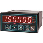
 Low Cost Process Meter | Panel Mount | Intuitive-Lite4-PBasic model, no plug-in optionsFrom £224Buy Online
- Universal Process Input Digital Indicator | Intuitive4-PHighly configurable, modular constructionFrom £252Buy Online
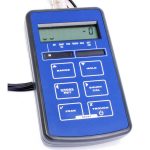
- Handheld Load Cell Indicator | Digital Display | TR150From £495Buy Online
- T24 Wireless Telemetry
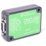
- USB Load Cell Interface | DSCUSB100 Readings/Second max.From £335Buy Online


Popular Products
- Platform Load Cell | Single Point Load Cell | 0-250g to 0-40kg | OBUG0-250g to 0-40kgFrom £128Buy Online
- Pancake Load Cell | Low Profile Force Sensor | DSCC0-5kN up to 0-1000kNFrom £651Buy Online
- Universal Load Cell | Universal S-Beam Force Sensor | DBBSM0-1kg up to 0-30,000kgFrom £269Buy Online
- Handheld Load Cell Indicator | Digital Display | TR150From £495Buy Online
- Strain Gauge Displacement Sensor | Linear Position Sensor | AML/SGD0-5mm to 0-100mmFrom £429Buy Online