At a Glance
- Individual Sensor Gain Adjustment
- 6-wire Connection (AMLJBA > Instrument)
- Robust IP65-rated ABS Enclosure
- IP67-rated Cable Glands
- Balance & Sum the Signals of up to 4 Load Cells
- Ideal for Multi Load Cell Applications
- Fast & Simple Installation with Screw Connection Terminals
- Suitable for Harsh Environments – Total Dust & Low Pressure Water Jet Protected
Description
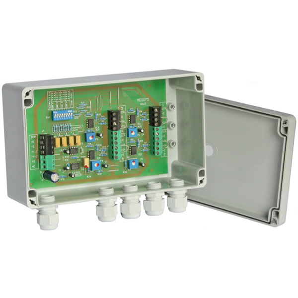
The AMLJBA is an active load cell junction box designed to enable up to four strain gauge based transducers to be connected and their signals balanced and summed.
The AMLJBA active junction box is ideal for multiple load cell applications where it is important that the millivolt signals from each of the load cells is very closely matched. Typical applications include, weighing platforms, weighbridges and vessel weighing systems.
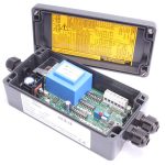
To enable swift and secure connection of the load cells a series of screw terminals are mounted on the internal circuit board of the junction box. Also mounted on the same board is a DIL switch to set the number of load cells being used and fine adjustment potentiometers to match the load cell sensitivities.
The active load cell junction box PCB is housed in a robust polycarbonate enclosure with glanded entry for the load cell cables, making the AMLJBA suitable for use in harsh environments requiring a sealing rating up to IP65.
For applications where the only interconnection is required, the passive AMLJBNA load cell junction box offers a lower-cost option.
Suitable instrumentation for connection through the AMLJBA active load cell junction box can be found in our range of Panel Indicators and Signal Conditioners.
Technical Specifications
| Electrical Specifications | ||
| Power Supply | 5-10 | Vdc (sourced from the host's excitation supply) |
| Current Requirement | 12 | mA (excluding strain gauge excitation current |
| Input Range | 0.5 to 20 | mV/V |
| Bridge Resistance | 350 | Ohms (The sum of the load cell excitation currents must not exceed the capability of the host) |
| Zero | ±0.03 | mV |
| Zero Temperature Coefficient | 0.0014 | %FR/°C (2.5mV/V @ 4V excitation) |
| Gain Temperature Coefficient | 0.005 | %/°C |
| Channel Gain Adjustment | 0.2 - 1.1 | |
| Output Gain Adjustment | ±12 | % |
| Environmental | ||
| Storage Temperature | -55 to +125 | °C |
| Operating Temperature | -40 to +80 | °C |
| Maximum Humidity | 95 | % non-condensing |
| Approvals | ||
| European EMC Directive | 2004/108/EC | |
| Low Voltage Directive | 2006/95/EC | |
| Dimensions | 200 x 120 x 75mm ABS | |
| Switch Settings | |||||||||
|---|---|---|---|---|---|---|---|---|---|
| Number of Strain Gauges Connected | SW1-1 | SW1-2 | SW1-3 | SW1-4 | SW1-5 | SW1-6 | SW1-7 | SW1-8 | Gain Range (via preset) |
| 1 | ON | ON | OFF | OFF | OFF | OFF | OFF | OFF | x 1 – 0.5 |
| 2 | OFF | ON | OFF | ON | OFF | OFF | OFF | OFF | x 0.33 – x 0.5 |
| 3 | ON | OFF | ON | OFF | ON | OFF | OFF | OFF | x 0.25 – 0.33 |
| 4 | OFF | OFF | OFF | OFF | OFF | OFF | OFF | OFF | OFF |
The unit is designed for 4 wire Strain Gauges, should 6 wire Strain Gauges be used, their excitation and sense wires should be both connected to the appropriate ‘E’ terminals. The 4 channels can be matched by adjusting the ‘Channel Gain’ potentiometers having first set the DIL switches for the number of Strain Gauges used. If access to individual Strain Gauges is possible eg before the platform or hopper is in position, then calibration can be carried out by placing a weight on one of the cells and noting the change in display reading on the ADW15.
Repeat this for each remaining Strain Gauge, and adjust the ‘Channel Gain’ potentiometers, to give the same change in display reading for each cell used.
Should the platform already be in the position it will be necessary to use a millivolt source to carry out the calibration. Apply a voltage of 10 times the millivolt/volt figure given for the appropriate Strain Gauge, to each channel in turn, adjusting the ‘Channel Gains’ to give equal changes in display readings for each cell used.
Product Dimensions
V2.0
Due to our policy on ongoing development, dimensions and specifications may change without notice.
Why Applied Measurements?
- Suppliers of top quality strain gauge sensors and transducers to every corner of industry - UK and worldwide
- Over 100 years of expert transducer knowledge
- Our high quality products all come with a 3 year warranty
Related Products
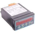
 Load Cell Digital Indicator | High Accuracy | Intuitive4-LHighly configurable, modular constructionFrom £364Buy Online
- Load Cell Amplifier | Load Cell Signal Conditioner | SGAInputs from 0.06mV/VFrom £235Buy Online
Popular Products
- Platform Load Cell | Single Point Load Cell | 0-250g to 0-40kg | OBUG0-250g to 0-40kgFrom £128Buy Online
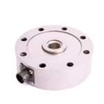
- Pancake Load Cell | Low Profile Force Sensor | DSCC0-5kN up to 0-1000kNFrom £651Buy Online
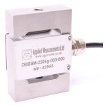
- Universal Load Cell | Universal S-Beam Force Sensor | DBBSM0-1kg up to 0-30,000kgFrom £269Buy Online
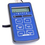
- Handheld Load Cell Indicator | Digital Display | TR150From £495Buy Online
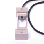
- Strain Gauge Displacement Sensor | Linear Position Sensor | AML/SGD0-5mm to 0-100mmFrom £429Buy Online