At a Glance
- Capacities: 0-50N/0-1Nm to 0-250kN/0-2500Nm
- Accuracy: <±0.1%/RC
- Low Crosstalk
- Environmental Protection: IP65
- Custom Versions Available
- Reduced Cross Talk Guarantees Optimum Performance
- Ideal for use in the Geotechnical and Materials Testing Sectors
- Customisation Available to Suit Your Specific Application
- Ideal for use in Most Industrial Environments
Description
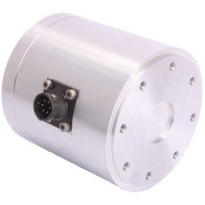
Applied Measurements DBBSS/TSF dual axis force and torque sensor is a compact and accurate transducer designed to measure both static torque and axial load in clockwise and counter-clockwise / tension and compression respectively.
The unique design of the 2-axis force and torque sensor ensures that crosstalk between the axes is minimised, with less than 1% being typical, whilst maintaining an excellent accuracy of better than 0.1% of rated capacity in both torque and force modes.
A 2 axis load cell provides a convenient way of measuring forces in two perpendicular directions simultaneously, making it a valuable tool in applications where multidirectional forces need to be accurately monitored and analysed.
Applied Measurements DBBSS/TSF 2 axis force and torque sensor series is used widely in the geotechnical and materials testing sectors where it is employed as a central component on pieces of high accuracy analytical test equipment, although its design lends itself to a huge range of other applications where dual-axis measurement is required.
The nature applications where the 2 axis force and torque sensor may be used is likely to require customisation in terms of size, capacity and the configuration of mounting holes or fixtures, and so we are pleased to say that design modifications to fit the DBBSS/TSF to your application can be offered with little or no effect on cost.
Have a look at our wide range of torque sensors, some of which can be customised to suit your application.
Technical Specifications
| Rated Capacity (RC) | N/Nm (Fz/Mz) | 0-50/0-1; 0-100/0-2; 0-250/0-5; 0-500/0-10 |
| Rated Capacity (RC) | kN/Nm (Fz/Mz) | 0-1/0-10; 0-2.5/0-25; 0-5/0-50; 0-10/0-100; 0-25/0-250; 0-25/0-500; 0-50/0-500; 0-100/0-1000; 0-250/0-2500 |
| Operating Modes | Tension/Compression / Tension & Compression | |
| Sensitivity (RO) (Force & Torque Outputs) | mV/V | 1 typical (0.5 typical on 0-50N/0-1Nm and 0-100/0-2Nm versions) |
| Zero Balance/Offset | ±%/Rated Output | 1 |
| Output Symmetry | ±%/Rated Output | <0.5 typical |
| Non-Linearity | ±%/Rated Output (BFSL) | Axial Force <0.05 / Torque <0.10 |
| Hysteresis | ±%/Rated Output | <0.1 |
| Repeatability | ±%/Rated Output | Axial Force <0.03 / Torque <0.05 |
| Temperature Effect on Zero | ±%/Rated Output/ ˚C | <0.01 |
| Temperature Effect on Sensitivity | ±%/Applied Load/ ˚C | <0.005 |
| Crosstalk | % | 0.1 to 1 typical |
| Input Resistance | Ohms | 400 nominal (Force Axis) 750 nominal (Torque Axis) |
| Output Resistance | Ohms | 350 nominal (Force Axis) 700 nominal (Torque Axis) |
| Insulation Resistance | Megohms | >5000 @ 50Vdc |
| Excitation Voltage | Volts AC or DC | 10 recommended (2-15 acceptable) |
| Operating Temperature Range | ˚C | -20 to +80 |
| Compensated Temperature Range | ˚C | 0 to +70 |
| Storage Temperature Range | ˚C | -20 to +80 |
| Safe Overload | % of Rated Capacity | 150 |
| Ultimate Overload | % of Rated Capacity | 300 |
| Maximum Safe Side Load | %/Rated Force Capacity | 30 |
| Deflection @ Rated Capacity | Consult sales | |
| Fundamental Resonant Frequency* | Consult sales | |
| IP Rating (Environmental Protection) | IP65 | |
| Weight (excluding cable) | See dimension table | |
| Fatigue Life | Consult Sales | |
| Cable Length (as standard) | metres | 5 |
| Electrical Connection | 6-Pin Bayonet Lock Connector + Mating Cable Assembly Fitted with 5 Metres of 6-Core Screened Cable | |
| Construction | Stainless Steel + Aluminium (0-500N/0-10Nm + below) / Stainless Steel (0-1kN/0-10Nm + above) | |
| Resolution: | 1 part in 250,000 (with appropriate instrumentation) | |
| *The resonant frequency is calculated with the body of the load cell attached to a large plate, ensuring that only the sensing element oscillates: This is vital to achieve the highest natural frequency and subsequent frequency response. | ||
Product Dimensions
| CAPACITY (Fz/Mz) | ØA | B | ØC | D | E | ØF | ØG | WEIGHT (kg) |
|---|---|---|---|---|---|---|---|---|
| 0-50N/0-1Nm, 0-100N/0-2Nm, 0-250N/0-5Nm, 0-500N/0-10Nm | 66 | 80 | 20/H7 | 6 | M4 x 6DP | 50 | 59 | 0.8 |
| 0-1kN/0-10Nm, 0-2.5kN/0-25Nm, 0-5kN/0-50Nm | 84 | 86 | 25/H7 | 8 | M5 x 7DP | 64 | 76 | 3.5 |
| 0-10kN/0-100Nm, 0-25kN/0-250Nm, 0-25kN/0-500Nm | 86 | 120 | 25/H7 | 6 | M8 x 12DP | 60 | 78 | 4.5 |
| 0-50kN/0-500Nm, 0-100kN/0-1000Nm | 135 | 125 | 30/H7 | 12 | M10 x 15DP | 100 | 125 | 11 |
| 0-250kN/0-2500Nm | 230 | 200 | 35/H7 | 12 | M16 x 24DP | 190 | 218 | 47 |
All dimensions are in mm
Wiring Details
| Wire / Pin | Designation |
|---|---|
| Red / Pin A | +ve excitation (common to both axes) |
| Blue / Pin B | -ve excitation (common to both axes) |
| Green / Pin C | +ve signal (Force Axis) (Compression) |
| Yellow / Pin D | -ve signal (Force Axis) |
| White / Pin E | +ve signal (Torque Axis) (Clockwise) |
| Black / Pin F | -ve signal (Torque Axis) |
Ordering Codes & Options
| Core Product | Capacity (inc Engineering Units) | Cable Length (m) | Specials Code | Example Result |
|---|---|---|---|---|
| DBBSS-TSF | 50N/1Nm | 005 | 000 | DBBSS-TSF-50N-1Nm-005-000 |
| DBBSS-TSF | 100N/2Nm | 005 | 000 | DBBSS-TSF-100N-2Nm-005-000 |
| DBBSS-TSF | 250N/5Nm | 005 | 000 | DBBSS-TSF-250N-5Nm-005-000 |
| DBBSS-TSF | 500N/10Nm | 005 | 000 | DBBSS-TSF-500N-10Nm-005-000 |
| DBBSS-TSF | 1kN-10Nm | 005 | 000 | DBBSS-TSF-1kN-10Nm-005-000 |
| DBBSS-TSF | 2.5kN-25Nm | 005 | 000 | DBBSS-TSF-2.5kN-25Nm-005-000 |
| DBBSS-TSF | 5kN-50Nm | 005 | 000 | DBBSS-TSF-5kN-50Nm-005-000 |
| DBBSS-TSF | 10kN-100Nm | 005 | 000 | DBBSS-TSF-10kN-100Nm-005-000 |
| DBBSS-TSF | 25kN-250Nm | 005 | 000 | DBBSS-TSF-25kN-250Nm-005-000 |
| DBBSS-TSF | 25kN-500Nm | 005 | 000 | DBBSS-TSF-25kN-500Nm-005-000 |
| DBBSS-TSF | 50kN-500Nm | 005 | 000 | DBBSS-TSF-50kN-500Nm-005-000 |
| DBBSS-TSF | 100kN-1000Nm | 005 | 000 | DBBSS-TSF-100kN-1000Nm-005-000 |
| DBBSS-TSF | 250kN-2500Nm | 005 | 000 | DBBSS-TSF-250kN-2500Nm-005-000 |
Published Sensor Application Articles
Below is a selection of published sensor application papers and journals that show you how the DBBSS-TSF force and torque sensor could be used in specific applications. See our published sensor application articles page for many more.
By Grégory S. Payne, Tim Stallard, Rodrigo Martinez, Renewable Energy Volume 107, July 2017, Pages 312-326 Available under a Creative Commons Attribution 4.0 International license.
Experimental Investigation of Tidal Rotor Loading due to Wave, Current and Impact with Sea Animals
By Payne, G, Stallard, T & Martinez, R 2015, Experimental Investigation of Tidal Rotor Loading due to Wave, Current and Impact with Sea Animals. in 11th European Wave and Tidal Energy Conference, Nantes, France. Available as open access.
Case Studies
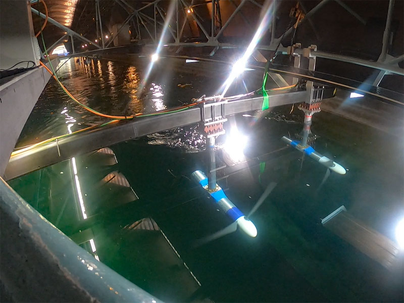
Applied Measurements Promise Precise Thrust & Torque Results in Tidal Turbine Testing
Read how our dual axis force and torque sensors was used in tidal testing by the University of Oxford. They aimed to understand how the spacing between tidal turbines and different control strategies affects the performance of tidal turbines.
Related Products
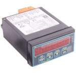 Load Cell Digital Indicator | High Accuracy | Intuitive4-LHighly configurable, modular constructionFrom £364Buy Online
 Large Digit Load Cell DisplayFrom £503
 Handheld Load Cell Indicator | Digital Display | TR150From £495Buy Online
 T24 Wireless Telemetry
 Miniature Load Cell Amplifier | In-Cell Amplifier | ICAFrom £85Buy Online
 Load Cell Amplifier | Load Cell Signal Conditioner | SGAInputs from 0.06mV/VFrom £235Buy Online
 USB Load Cell Interface | DSCUSB100 Readings/Second max.From £335Buy Online