At a Glance
- Capacities: 0-0.7kN up to 0-5kN
- Output: 2mV/V ±0.1%
- Hermetically Sealed
- Fully Submersible IP68 Rated to 2m/0.2bar
- Simple To Install
- High Accuracy: <±0.02%/FS
- Designed for Permanent Long-Term Submersion to 2m/0.2bar
- Ideal for Hydrostatic Testing and Off-Shore Applications
- Hermetically Sealed – Ideal for Harsh Industrial Environments
- Improved Accuracy – With our specially designed rod end bearings which reduce extraneous forces.
- Fast and Simple Installation – With standard or customised mounting bases and design fixtures.
Description
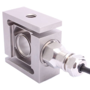
Applied Measurements DBBSUB submersible S-Beam load cell is ideal for tension and compression measurement in situations involving permanent submersion in water. They are hermetically sealed to IP68 to a depth of 2m/0.2bar making them ideal for flood susceptible locations, submersible and hydrostatic applications.
The permanently submersible s-beam load cell has a dual bending beam design to ensure inherently high accuracy and enables us to guarantee performance well within specification.
Our DBBSUB permanently submersible load cell can be supplied with specialised rod end bearings further guaranteeing the transducer’s optimum performance. For fast and simple installation they can be supplied with custom designed mounting plates and fixtures.
If you require an IP67 rated S-Beam load cells with capacities of less than 50kg or greater than 10,000kg, our DBBSM series of S-Beam load cells covers load ranges from 0-1kg (10N) up to 0-30,000kg (300kN). Meanwhile, if you need to fit into a restricted space, Applied Measurements DBBSMM range of miniature S-Beam load cells will fit the bill.
Technical Specifications
| Rated Capacity (RC) | kN | 0-0.7, 0-1, 0-2, 0-5 |
|---|---|---|
| Operating Modes | Tension/Compression / Tension & Compression | |
| Sensitivity (RO) | mV/V | 2 ± 0.1% (1±0.2% on 0.5kN capacity) |
| Pressure Sensitivity | %/FS/bar (metre) | ±0.05 (±0.005) |
| Zero Balance/Offset | ±%/Rated Output | ±5 |
| Zero Return after 30 mins | ±%/Applied Load | ±0.02 |
| Output Symmetry (tension vs. compression) | ±%/Rated Output | ±0.1 |
| Non-Linearity | ±%/Rated Output (BFSL) | ±0.02 |
| Hysteresis | % / Rated Output | ±0.02 |
| Repeatability | ±%/Rated Output | ±0.02 |
| Temperature Effect on Zero | ±%/Rated Output/˚C | ±0.02 |
| Temperature Effect on Sensitivity | ±%/Rated Output/˚C | ±0.01 |
| Input Resistance | Ohms | 1100 ± 50 |
| Output Resistance | Ohms | 1000 ± 2 |
| Insulation Resistance | Megohms | >5000 @ 100Vdc |
| Excitation Voltage | Volts AC or DC | 10 recommended (5-15 acceptable) |
| Operating Temperature Range | ˚C | -40 to +80 (ATEX -40 to +60) |
| Compensated Temperature Range | ˚C | -10 to +40 |
| Storage Temperature Range | ˚C | -40 to +80 |
| Safe Overload | % of Rated Capacity | 200 |
| Ultimate Overload | % of Rated Capacity | 300 |
| Deflection @ Rated Capacity | mm | 0.3 nominal |
| Fundamental Resonant Frequency* | Hz | see dimensional table |
| IP Rating (Environmental Protection) | IP68 up to 2m water depth/0.2bar | |
| Weight (excluding cable) | kg | 1.0 (1kN, 2 kN), 1.1(5kN) |
| Fatigue Life | 108 cycles typical (109 cycles on fatigue-rated version) | |
| Cable Length (as standard) | metres | 6m |
| Cable Type | Shielded, 4 conductor cable (AWG 24) Ø5mm, Cable jacket polyurethane (PUR) | |
| Construction Material | 17-4 PH Stainless Steel Body. 303 Stainless Steel (Cable Gland) | |
| Resolution | 1 part in 250,000 (with appropriate instrumentation) | |
| *The resonant frequency is calculated with the body of the load cell attached to a large plate, ensuring that only the sensing element oscillates: This is vital to achieve the highest natural frequency and subsequent frequency response. | ||
Product Dimensions
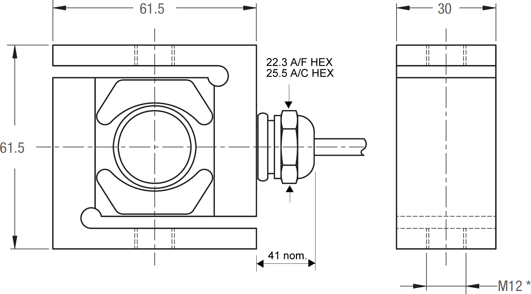
| Capacity (kN) | H | L | W | Threads T | Resonant Frequency Hz |
|---|---|---|---|---|---|
| 0.7 | 61.5 | 61.5 | 30 | M12 | 400 |
| 1 | 61.5 | 61.5 | 30 | M12 | 500 |
| 2 | 61.5 | 61.5 | 30 | M12 | 700 |
| 5 | 61.5 | 61.5 | 30 | M12 | 1000 |
All dimensions are in mm
Wiring Details
| Wire | Designation |
|---|---|
| Green | +ve excitation |
| Black | -ve excitation |
| White | +ve signal |
| Red | -ve signal |
| Shield | To ground - not connected to load cell body |
Ordering Codes & Options
| Core Product | Capacity (inc Engineering Units) | Cable Length (m) | Specials Code | Example Result |
|---|---|---|---|---|
| DBBSUB | 0.7kN | 006 | 000 | DBBSUB-0.7kN-006-000 |
| DBBSUB | 1kN | 006 | 000 | DBBSUB-1kN-006-000 |
| DBBSUB | 2kN | 006 | 000 | DBBSUB-2kN-006-000 |
| DBBSUB | 5kN | 006 | 000 | DBBSUB-5kN-006-000 |
How To Install An S-Beam Load Cell
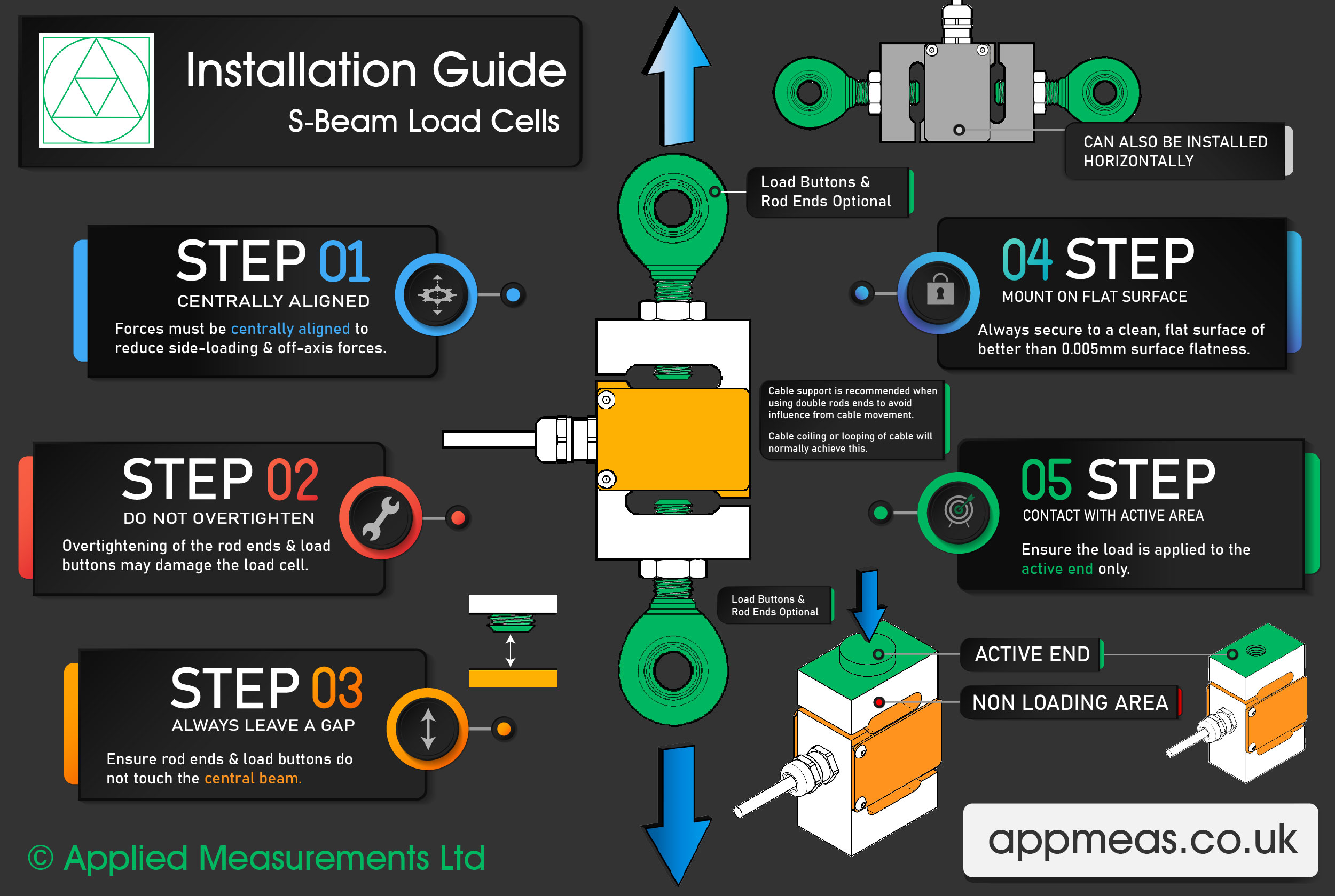
Our Applied Measurements experts have put together a 5-step guide to demonstrate how to correctly install an S-beam load cell.
Step 1 – Keep the Forces Centrally Aligned
To reduce any off-axis loading, forces must be centrally aligned through the centre of the load cell. We can supply optional load buttons and rod ends which work to reduce any side loading.
Step 2 – Do Not Overtighten the Rod Ends and Load Buttons
When using rod ends and load buttons be sure not to overtighten them when attaching them to the S-beam load cell. As this can cause damage to the load cell.
Step 3 – Always Leave a Gap
Ensure that the rod ends and load buttons do not touch the central beam. If a gap is not maintained, the central beam will not be able to move freely when tension or compressive force is applied.
Step 4 – Mount on a Flat Surface
Always secure the S-beam load cell to a clean, flat surface of better than 0.005mm surface flatness.
Step 5 – Contact with Active Area Only
When installing the S-beam load cell ensure the load is applied to the active end area only.
Related Products
 Load Cell Digital Indicator | High Accuracy | Intuitive4-LHighly configurable, modular constructionFrom £364Buy Online
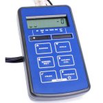 Handheld Load Cell Indicator | Digital Display | TR150From £495Buy Online
 T24 Wireless Telemetry
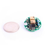 Miniature Load Cell Amplifier | In-Cell Amplifier | ICAFrom £85Buy Online
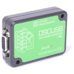 USB Load Cell Interface | DSCUSB100 Readings/Second max.From £335Buy Online