At a Glance
- Torque Ranges: 0-10Nm to 0-20kNm
- Selectable Torque Units: Nm, mNm, lb-ft, in-lb, oz-in, g-cm
- High Accuracy: <±0.1% of Capacity
- Portable, Battery-Powered Display
- Static Torque Transducer + Digital Meter Readout
- Ideal for Fastening or Breakaway Torque of Bolts and Nuts
- Supplied Calibrated & Ready to Use
- Dust-Tight and Splash-Proof
- 128 x 64 Monochrome Dot Matrix Display
Description
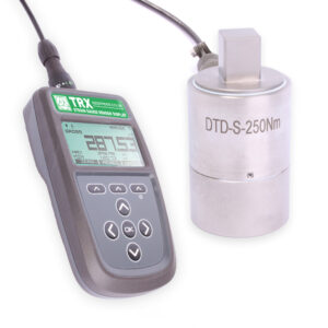
Applied Measurements Torque Measurement System is a complete, portable torque testing system. It is supplied ready calibrated, to UKAS-traceable standards, with a high-resolution digital meter, enabling you to undertake fast, portable, torque testing and monitoring.
The reaction / static torque transducer DTD-S has a square drive and is designed to measure the fastening or breakaway torque of bolts and nuts. Plus, this torque tester system is ideal for calibrating automated torque screwdrivers, spanners and wrenches.
Thanks to the high accuracy of the static torque transducer of better than ±0.1% of rated capacity, our torque meter systems are perfect for the calibration or testing of torque tools in a QA environment.
The torque meter system has an IP65 dust-tight and splash-proof protection as standard making it suitable for most industrial environments. What’s more, the torque transducer can be customised with improved sealing up to IP68 submersible for applications where operating conditions are harsh or involve long-term submersion.
The torque meter system comes with a high resolution 128 x 64 monochrome dot matrix display and is protected to an IP64 dust-tight, splash proof rating. It features peak & trough capture and display hold/freeze options.
The digital meter’s six range capability means it can be calibrated to work with up to six different sensors if you need to cover a range of different torque levels, although please note that due to the fact that there is only one cable input, only one sensor at a time can be monitored.
Need an integrated torque meter and display? Try our DRBK-A Low Cost Rotary Torque Sensor with Display which features a built-in 4 segment LCD display giving you instant torque and speed readings with real-time speed updates of 1x sample/second and torque updates of 1,000 sample per second.
Technical Specifications
DTD-S Static Torque Transducer Dimensions
| Capacity (Nm) | Square Drive A | B | C | ØD |
|---|---|---|---|---|
| 10 | 0.250 inch | 7.5 | 48 | 25 |
| 20 | 0.250 inch | 7.5 | 48 | 25 |
| 50 | 0.375 inch | 11.5 | 58 | 35 |
| 100 | 0.500 inch | 15.5 | 58 | 35 |
| 200 | 0.750 inch | 23 | 79 | 54 |
| 250 | 0.750 inch | 23 | 79 | 54 |
| 500 | 0.750 inch | 23 | 79 | 54 |
| 1000 | 1.000 inch | 28 | 79 | 54 |
| 2000 | 1.500 inch | 38 | 95 | 70 |
| 5000 | 2.000 inch | 45 | 130 | 90 |
| 10000 | 2.500 inch | 55 | 165 | 110 |
| 20000 | 3.000 inch | 68 | 212 | 130 |
| 50000 | 3.500 inch | 79 | 185 | 180 |
| Rated Capacity (RC) | Nm | 0-10, 0-20, 0-50, 0-100, 0-200, 0-250, 0-500, 0-1000, 0-2k, 0-5k, 0-10k, 0-20k, 0-50k |
|---|---|---|
| Operating Modes | Clockwise (CW)/Counter-Clockwise (CCW) / Clockwise (CW) & Counter-Clockwise (CCW) | |
| Sensitivity (RO) | mV/V | 1.5 nominal |
| Zero Balance/Offset | ±%/Rated Output | <1 |
| Output Symmetry (CW vs. CCW) | ±%/Rated Output | <0.25 typical |
| Non-Linearity | ±%/Rated Output (BFSL) | <0.1 |
| Hysteresis | ±%/Full Scale Output | <0.1 |
| Repeatability | ±%/Full Scale Output | <0.1 |
| Temperature Effect on Zero | ±Full Scale Output/ ˚C | <0.010 |
| Temperature Effect on Output | ±/Reading/ ˚C | <0.010 |
| Bridge Resistance | Ohms | 700 nominal |
| Insulation Resistance | Megaohms | >5000 @ 50Vdc |
| Excitation Voltage | Volts AC or DC | 10 recommended (2-15 acceptable) |
| Operating Temperature Range | ˚C | -20 to +80 |
| Compensated Temperature Range | ˚C | +20 to +70 |
| Storage Temperature Range | ˚C | -20 to +80 |
| Safe Overload | % of Rated Capacity | 150 |
| Ultimate Overload | % of Rated Capacity | 300 |
| IP Rating (Environmental Protection) | IP65 | |
| Weight | See dimensions table | |
| Fatigue Rating | 108 cycles typical | |
| Cable Length (as standard) | metres | 3 |
| Cable Type | 4-core screened PUR, Ø4.6mm | |
| Construction | Stainless Steel | |
| Resolution | 1 part in 250,000 (with appropriate instrumentation) | |
TRX Dimensions
| CHARACTERISTICS | Min | Typical | Max | Units |
|---|---|---|---|---|
| Strain Gauge Measurement | 6-wire | Can also accept a 4-wire input. | ||
| Display | 128 x 64 dot matrix display with backlight | |||
| Resolution at 1 SPS | 1,100,000 (20) | Counts (bit) | ||
| Resolution at 10 SPS | 550,000 (19) | Counts (bit) Noise-free at ±7.5 mV/V range | ||
| Resolution at 2,400 SPS | 6,500 (14.3) | Counts (bit) | ||
| Linearity | ±2 | ppm/FSR In high-quality operating mode (Linearity error can be further reduced by device linearization calibration) |
||
| Excitation | 3.2 | 3.3 | 3.4 | Vdc |
| Drive Capability | 85 | - | 10,000 | Ohm |
| Sensitivity | ±7.5 | - | ±480 | mV/V (Effective sensitivity from ±0.5mV/V with reduced resolution) |
| Offset Temperature Stability | 12 | nV/°C At 2.5 mV/V | ||
| Gain Temperature Stability | 1 | 2 | ppm/°C | |
| Internal Resolution | 24 | bit | ||
| Display Resolution | 128 x 64 | Pixels | ||
| Buzzer Acoustic Output | 45 | dB | ||
| Power Supply | 2x 1.5V AA (LR6) batteries or USB powered | Operation with batteries rated below 1.5V is not guaranteed to provide specified performance. | ||
| Power Consumption | 35 | mA (in normal measurement mode) | ||
| Standby Current | 75 | μA | ||
| Battery Life Low Quality 1Hz | 220 | Hrs | ||
| Battery Life High Quality 1,200Hz | 60 | Hrs | ||
| Operating Temperature Range | -10 | +50 | °C | |
| Storage Temperature Range | -20 | +80 | °C | |
| Operating Humidity Range | 0 | 95 | %RH | |
| Environmental Protection | IP64 (With connector mated or unmated) | |||
| External Dimensions | L: 170 mm, W: 94 mm, H: 42 mm (excluding mated connector) | |||
| Weight | 365 | g including batteries | ||
| Core Product | Details | Example Result |
|---|---|---|
| TRX Portable Strain Gauge Display | Standard Version with 6 Calibration Ranges, includes one Micro-USB Right Angle Cable | TRX-A |
| Additional Micro-USB Right Angle Cable | Cable only | Speak to Sales |
| Suction Mount for TRX Strain Gauge Sensor Display | Suction mount only | Speak to Sales |
| Screw Mount for TRX Strain Gauge Sensor Display | Screw mount only | Speak to Sales |
| Leather and plastic protective case accessory for the TRX Strain Gauge Sensor Display | Case only | Speak to Sales |
Related Products
 Load Cell Digital Indicator | High Accuracy | Intuitive4-LHighly configurable, modular constructionFrom £364Buy Online
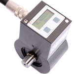 Low Cost Rotary Torque Sensor with Display | DRBK-A0-0.5Nm to 0-1000NmFrom £3,014Buy Online
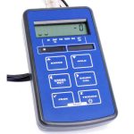 Handheld Load Cell Indicator | Digital Display | TR150From £495Buy Online
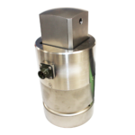 Square Drive Static Torque Transducer | DTD-S0-10Nm to 0-50kNmFrom £911