At a Glance
- Stroke Ranges: ±0.5mm to ±500mm
- AC mV/V or DC Voltage / Current Output
- Environmental Protection: IP65
- Core + Extension, Spring-Loaded & Rod-End Bearing Versions
- Optional IP68 Submersible &
- High-Temperature Versions 200°C and 150°C
- Ideally Suited for Harsh Industrial Environments
- Fully Submersible & High-Temperature 200°C & 150°C Versions Available
- Wide Range of Mechanical Configurations to Suit Your Specific Application
- Fast and Simple Installation – With our wide variety of packaging formats.
- Long Operating Life – No physical contact between the core and the coils.
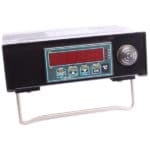
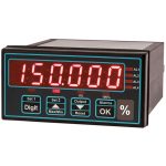
- Let us do the Hard Work for You – We can provide you with a wide range of supporting instrumentation.
Description
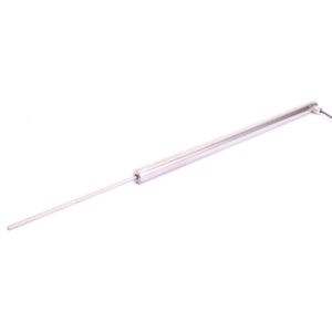
Applied Measurements AML/IE series of industrial LVDT displacement transducers are available with measuring ranges from ±0.5mm (0-1mm) up to ±500mm (0-1000mm).
Constructed from stainless steel, the AML/IE LVDTs are sealed to IP65 as standard with the option of IP68 (submersible), making them ideally suited for a multitude of harsh and demanding applications where environmental conditions are humid, wet, dusty or dirty.
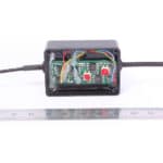
The basic AML/IE industrial LVDT displacement transducers have an AC mV/V output as standard, with a range of DC voltage signal output options also offered including 0-5Vdc, 0-10Vdc and ±2.5Vdc, as well as a 3-wire 4-20mA current output.
Applied Measurements AML/IE industrial LVDT offers a choice of mechanical configurations including captive guided core & extension rod, which is standard, plus spring-loaded core & extension rod with ball-end or guided core & extension with spherical rod-end bearings.
Please see our full range of LVDT displacement transducers and position sensors. We can also offer a comprehensive variety of supporting instrumentation. Contact Applied Measurements expert and friendly technical team to discuss your requirements.
Technical Specifications
| CHARACTERISTICS | AML/IE | AML/IEJ | AML/IEU | AML/IEU -10 | AML/IEI | AML/IED | UNITS |
|---|---|---|---|---|---|---|---|
| Stroke Measurement Range: | ±0.5, ±2.5, ±5, ±10, ±12.5, ±15, ±25, ±50, ±75, ±100, ±125, ±150, ±175, ±200, ±250 ±300, ±400, ±500, ±550 (maximum stroke is ±125 for Sprung Loaded Core & Extension) | millimetres | |||||
| Signal Output: | See Table Below | 0-5volt | 0-10volt | 4-20mA | ±2.5volt | ||
| No. of Wires | 6 | 4 | 3 | 3 | 3 | 4 | |
| Supply Voltage (unregulated): | 2 to 5Vrms @ 1 to 5kHz | 10-24Vdc | 14-24Vdc | 14-24Vdc | 12Vdc regulated | ||
| Supply Current: | - | 35mA @ 15V | 35mA @ 15V | 35mA typ. | 35mA @ 12V | ||
| Max. Loop Resistance: | - | - | - | 300 @ 30V | - | ohms | |
| Max. Output Sink Current: | - | 0.5 | 1 | - | 0.1 | milliamps | |
| Non-Linearity: | <0.50 | ±%/Rated Output (BFSL) | |||||
| Repeatability: | <0.10 | ±% Stroke Range | |||||
| Output Bandwidth (flat): | 100 | Hz | |||||
| Output Ripple: | - | 30mV max. | 30mV max. | 0.1% @ 20mA | 30mV max. | ||
| Operating Temperature Range: | AML/IE & IEJ: -30 to +85 Standard / -30 to +150 and +200 Optional -20 to +85 on DC/DC models / 0 to +70 for in-line conditioner (where fitted) | °C | |||||
| Zero Temperature Coefficient: | <0.020 | <0.010 | ±%Stroke Range/°C | ||||
| Span Temperature Coefficient: | <0.020 | <0.030 | ±%Stroke Range/°C | ||||
| Vibration Resistance: | 20g up to 2kHz | ||||||
| Shock Resistance: | 1000g for 10milliseconds | ||||||
| Construction Materials: | Body & Extension Rod: 303 St/Steel, Core: 416 St/Steel, Cable Gland: Nickel-Plated Brass, Spring: 316 St/Steel, Rod-End Bearings: Mild Steel (St/Steel on IP68 version) | ||||||
| Connecting Cable: | 2 metre screened PVC cable* (*IP68 = PUR / Hi-Temp = PTFE). | ||||||
| Environmental Sealing: | IP65 (IP68 optional) | ||||||
| Note: On DC output version (0Vdc / 4mA) is given with the core in the extended / outwards position. This can be reversed if required, please request Option Y on your order. |
|||||||
Product Dimensions
| Standard (Plain Core + Extension) | Standard and Option R | Option R (Rod End Bearings) |
||||||
|---|---|---|---|---|---|---|---|---|
| Stroke (mm) | Body Length (mm) | Sensitivity @ 3kHz with 50K Load (mV/V FRO) | Null (mV) | Primary Resistance (ohms) | Secondary Resistance (ohms) | Body Length (mm) | M6 "L" (mm) | M8 "L" (mm) |
| ±0.5 | 100 | 175 | 20 | 40 | 1800 | 100 | 168 | 171 |
| ±2.5 | 100 | 140 | 5 | 130 | 740 | 100 | 168 | 171 |
| ±5 | 115 | 135 | 5 | 48 | 108 | 120 | 188 | 191 |
| ±10 | 140 | 270 | 5 | 70 | 170 | 140 | 208 | 211 |
| ±12.5 | 160 | 195 | 5 | 120 | 190 | 160 | 228 | 231 |
| ±15 | 175 | 246 | 5 | 90 | 190 | 175 | 243 | 246 |
| ±25 | 235 | 225 | 5 | 130 | 210 | 235 | 303 | 306 |
| ±50 | 320 | 260 | 5 | 200 | 270 | 320 | 388 | 391 |
| ±75 | 390 | 390 | 20 | 260 | 460 | 390 | 458 | 461 |
| ±100 | 450 | 240 | 5 | 150 | 150 | 450 | 518 | 521 |
| ±125 | 500 | 260 | 5 | 180 | 320 | 500 | 568 | 571 |
| ±150 | 560 | 230 | 5 | 210 | 290 | 560 | 628 | 631 |
| ±175 | 615 | 260 | 2 | 230 | 360 | 615 | 683 | 686 |
| ±200 | 700 | 285 | 10 | 250 | 430 | 700 | 768 | 771 |
| ±250 | 810 | 310 | 10 | 290 | 560 | 810 | 878 | 881 |
| ±300 | 920 | 270 | 5 | 690 | 770 | 920 | 988 | 991 |
| ±400 | 1150 | 440 | 20 | 450 | 1010 | 1150 | 1218 | 1221 |
| ±500 | 1410 | 475 | 10 | 550 | 1530 | 1410 | 1478 | 1481 |
| ±550 | 1410 | 345 | 10 | 550 | 1530 | 1410 | 1478 | 1481 |
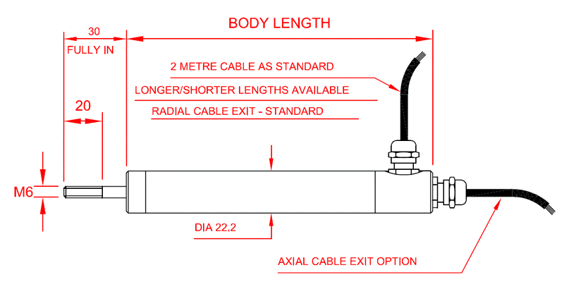
AML-IE Industrial LVDT Displacement Transducer AC Version Plain Outline 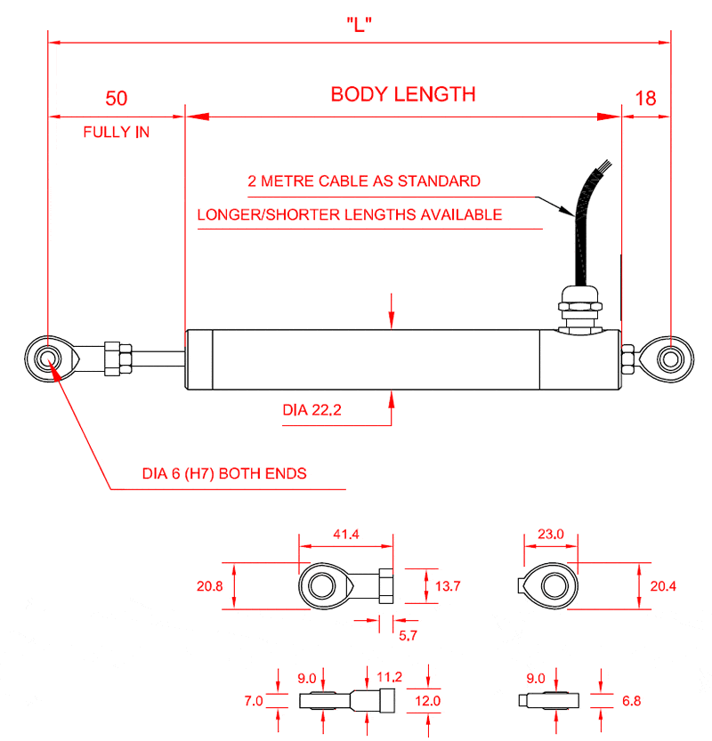
AML-IE Industrial LVDT Displacement Transducer AC Version with M6 Rod End Bearings (R+M6) Outline 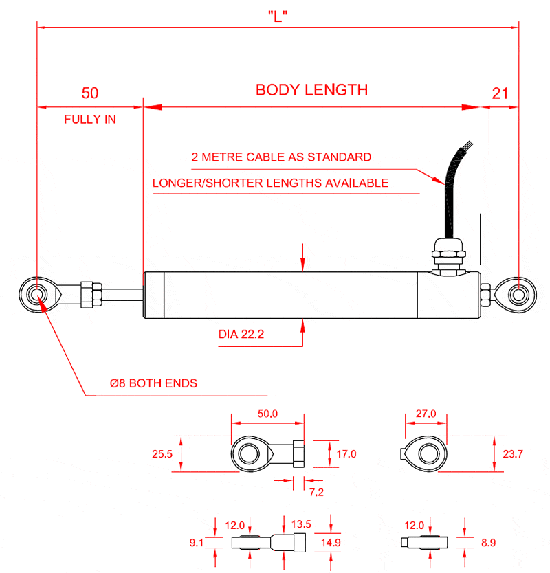
AML-IE Industrial LVDT Displacement Transducer AC Version with M8 Rod End Bearings (R+M8) Outline 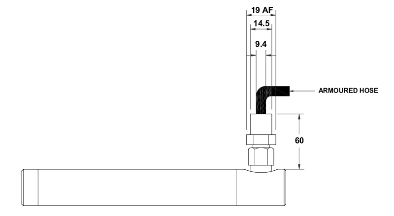
AML-IE Armoured Hose
Plain Core + Extension AML-IE Industrial AC Version Options: A = axial cable exit; R = radial cable exit; J = 4-wire device; G = extension rod wiper; W = waterproof IP68; H = high temperature 150°C with PTFE cable; VH = very high temperature 200°C with PTFE cable; Z = armoured hose.
Option R M6 AML-IE Industrial AC Version with M6 Rod End Bearings Options: R = radial cable exit ONLY; J = 4-wire device; G = extension rod wiper; W = waterproof IP68; H = high temperature 150°C with PTFE cable; VH = very high temperature 200°C with PTFE cable; Z = armoured hose.
Axial cable exit is NOT available with rod ends unless rod end is on the extension ONLY.
Option R M8 AML-IE Industrial AC Version with M8 Rod End Bearings Options: R = radial cable exit ONLY; J = 4-wire device; G = extension rod wiper; W = waterproof IP68; H = high temperature 150°C with PTFE cable; VH = very high temperature 200°C with PTFE cable; Z = armoured hose.
Axial cable exit is NOT available with rod ends unless rod end is on the extension ONLY.
| Stroke (mm) | Body Length (mm) | Sensitivity @ 3kHz with 50K Load (mV/V FRO) | Null (mV) | Primary Resistance (ohms) | Secondary Resistance (ohms) | Spring Rate (N/mm) |
|---|---|---|---|---|---|---|
| ±0.5 | 100 | 175 | 20 | 40 | 1800 | 0.2591 |
| ±2.5 | 100 | 140 | 5 | 130 | 740 | 0.2591 |
| ±5 | 115 | 135 | 5 | 48 | 108 | 0.1457 |
| ±10 | 160 | 270 | 5 | 72 | 138 | 0.0833 |
| ±12.5 | 160 | 195 | 5 | 72 | 138 | 0.0833 |
| ±15 | 175 | 246 | 5 | 90 | 190 | 0.0648 |
| ±25 | 235 | 225 | 5 | 130 | 210 | 0.0530 |
| ±50 | 320 | 260 | 5 | 200 | 270 | 0.0364 |
| ±75 | 390 | 390 | 20 | 260 | 460 | 0.0291 |
| ±100 | 440 | 240 | 20 | 260 | 460 | 0.0233 |
| ±125 | 525 | 260 | 5 | 145 | 230 | 0.0179 |
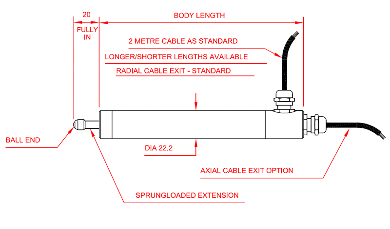
AML-IE Industrial LVDT Displacement Transducer AC Version Sprung-Loaded (S) Outline
Option S AML-IE AC Version Sprung Loaded Options: R = radial cable; A = axial cable; J = 4-wire device; G = extension rod wiper; SW = waterproof IP68; H = High Temperature 150°C, Z = armoured hose.
VH = high-temperature 200°C option not available on spring loaded.
| Standard | Option R (Rod End Bearings) | Option S (Sprung-Loaded) | ||||
|---|---|---|---|---|---|---|
| Stroke (mm) | Body Length (mm) | Body Length (mm) | M6 "L" (mm) | M8 "L" (mm) | Body Length (mm) | Spring Rate (N/mm) |
| ±0.5 | 130 | 130 | 198 | 201 | 130 | 0.1295 |
| ±2.5 | 140 | 140 | 208 | 211 | 140 | 0.1166 |
| ±5 | 165 | 165 | 233 | 236 | 165 | 0.0897 |
| ±10 | 180 | 180 | 248 | 251 | 180 | 0.0729 |
| ±12.5 | 210 | 210 | 278 | 281 | 210 | 0.0614 |
| ±15 | 225 | 225 | 293 | 296 | 225 | 0.0555 |
| ±25 | 285 | 285 | 353 | 356 | 285 | 0.0416 |
| ±50 | 370 | 370 | 438 | 441 | 370 | 0.0291 |
| ±75 | 440 | 440 | 508 | 511 | 440 | 0.0233 |
| ±100 | 500 | 500 | 568 | 571 | 440 | 0.0233 |
| ±125 | 550 | 550 | 618 | 621 | 525 | 0.0179 |
| ±150 | 610 | 610 | 678 | 681 | n/a | n/a |
| ±175 | 665 | 665 | 733 | 736 | n/a | n/a |
| ±200 | 750 | 750 | 818 | 821 | n/a | n/a |
| ±250 | 860 | 860 | 928 | 931 | n/a | n/a |
| ±300 | 970 | 970 | 1038 | 1041 | n/a | n/a |
| ±400 | 1200 | 1200 | 1268 | 1271 | n/a | n/a |
| ±500 | 1460 | 1460 | 1528 | 1531 | n/a | n/a |
| ±550 | 1460 | 1460 | 1528 | 1531 | n/a | n/a |
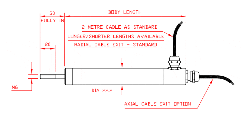
AML-IE Industrial LVDT Displacement Transducer DC Version Plain Outline 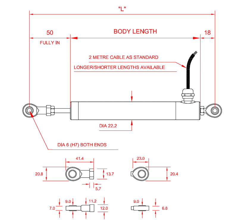
AML-IE Industrial LVDT Displacement Transducer DC Version with M6 Rod End Bearings (R+M6) Outline 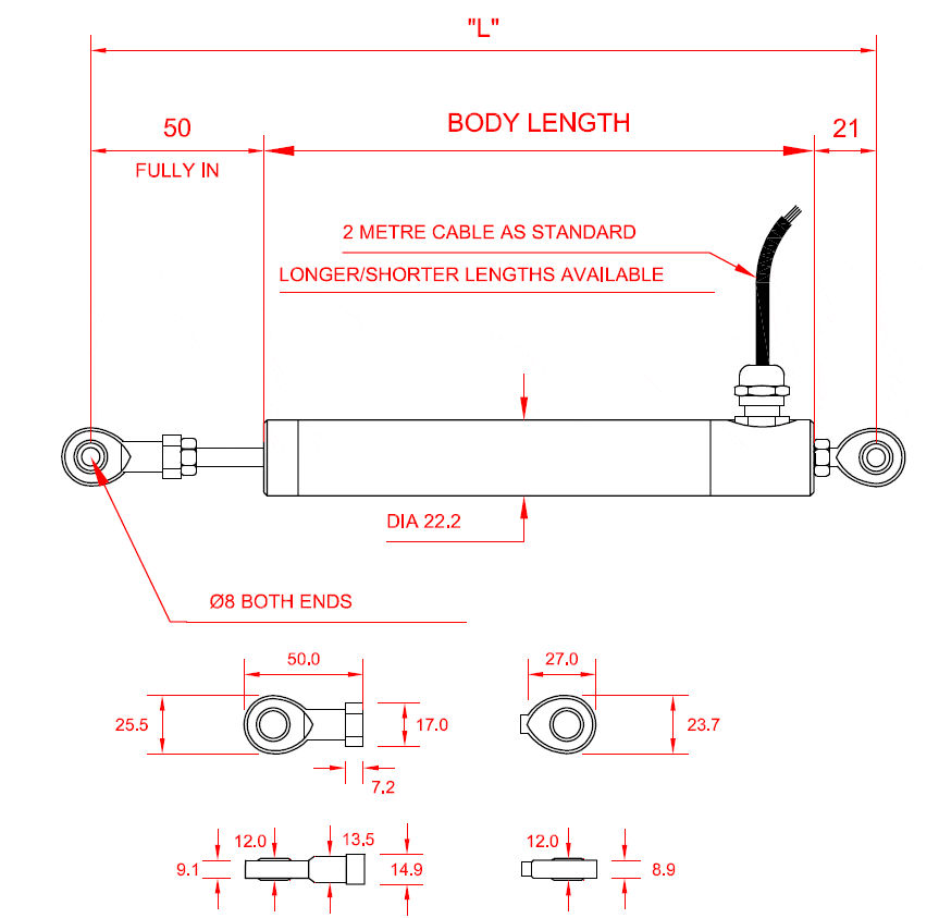
AML-IE Industrial LVDT Displacement Transducer DC Version with M8 Rod End Bearings (R+M8) Outline 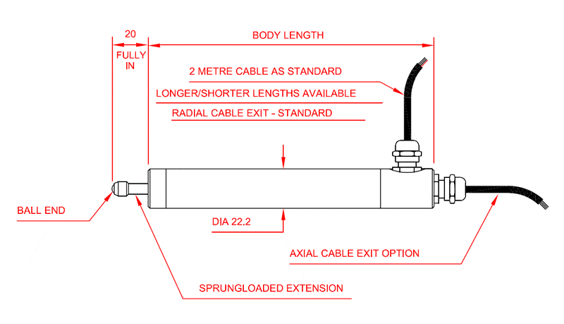
AML-IE Industrial LVDT Displacement Transducer DC Version Sprung-Loaded (S) Outline
Plain Core AML-IE Industrial DC Version Options: A = axial cable exit; R = radial cable exit; G = extension rod wiper; W = waterproof IP68 with PU cable; I = 4-20mA output; U = 0-5V output; U-10 = 0-10V output; D = DC bipolar output; Y = reverse output (e.g. 4mA fully in instead of default 20mA); Z = armoured hose.
H & VH = high temperature options not available
Option R M6 Rod Ends AML-IE Industrial Version with M6 Rod End Bearings Options: R = radial cable exit only; G = extension rod wiper; W = waterproof IP68 with PU cable and stainless steel M6 rod end bearings; I = 4-20mA output; U = 0-5V output; U-10 = 0-10V output; D = DC bipolar output; Y = reverse output (e.g. 4mA fully in instead of default 20mA); Z = armoured hose.
H & VH = high temperature options not available
Option R M8 Rod Ends AML-IE Industrial DC Version with M8 Rod End Bearings Options: R = radial cable exit only; G = extension rod wiper; W = waterproof IP68 with PU cable and stainless steel M8 rod end bearings; I = 4-20mA output; U = 0-5V output; U-10 = 0-10V output; D = DC bipolar output; Y = reverse output (e.g. 4mA fully in instead of default 20mA); Z = armoured hose.
H & VH = high temperature options not available
Option S AML-IE Industrial DC Version Sprung Loaded Options: R = radial cable exit; A = axial cable exit; G = extension rod wiper; W = waterproof IP68 with PU cable; I = 4-20mA output; U = 0-5V output; U-10 = 0-10V output; D = DC bipolar output; Y = reverse output (e.g. 4mA fully in instead of default 20mA); Z = armoured hose.
H & VH = high temperature options not available
Wiring Details
4-WIRE AC VERSION (PVC OR PTFE, HIGH TEMPERATURE 150˚C AND 200°C)
| Wire | Designation |
|---|---|
| Red | Primary +ve |
| Yellow | Primary -ve |
| Blue | Secondary +ve |
| Green | Secondary -ve |
| Ground | Screen (not connected to sensor body) |
6-WIRE AC VERSION (PVC)
| Wire | Designation |
|---|---|
| Yellow | Primary +ve |
| Black | Primary -ve |
| Green | Secondary 1 +ve |
| Red | Secondary 1 -ve (centre tap) |
| White | Secondary 2 +ve |
| Blue | Secondary 2 -ve (centre tap) |
| Ground | Screen (not connected to sensor body) |
6-WIRE AC VERSION (PTFE, HIGH TEMPERATURE 150°C AND 200°C)
| Wire | Designation |
|---|---|
| Yellow | Primary +ve |
| Black | Primary -ve |
| Green | Secondary 1 +ve |
| Red | Secondary 1 -ve (centre tap) |
| Brown | Secondary 2 +ve |
| Blue | Secondary 2 -ve (centre tap) |
| Ground | Screen (not connected to sensor body) |
3-WIRE DC VERSIONS (4-20MA, 0-5VDC, 0-10VDC, ±2.5VDC)
| Wire | Designation |
|---|---|
| Red | Supply |
| Blue | 0V Common |
| Green | Signal |
| Ground | Screen (not connected to sensor body) |
Ordering Codes & Options
| AML/IEU10+/-500mm-WR0A-0.2-000 (example code) | AML/IE | U10 | +/-500mm | - | WR | O | A | - | 0.2 | - | 000 |
|---|---|---|---|---|---|---|---|---|---|---|---|
| Product Family | |||||||||||
| AML/IE | AML/IE | ||||||||||
| Electrical Output | |||||||||||
| Blank = 6-wire AC mV/V | Blank | ||||||||||
| J = 4-wire AC mV/V | J | ||||||||||
| U = 0-5Vdc | U | ||||||||||
| U10 = 0-10Vdc | U10 | ||||||||||
| I = 4-20mA | I | ||||||||||
| D = ±2.5Vdc (12Vdc regulated supply required) | D | ||||||||||
| Stroke Range | |||||||||||
| +/-0.5mm (0-1mm) | +/-0.5mm | ||||||||||
| +/-2.5mm (0-5mm) | +/-2.5mm | ||||||||||
| +/-5mm (0-10mm) | +/-5mm | ||||||||||
| +/-10mm (0-20mm) | +/-10mm | ||||||||||
| +/-12.5mm (0-25mm) | +/-12.5mm | ||||||||||
| +/-15mm (0-30mm) | +/-15mm | ||||||||||
| +/-25mm (0-50mm) | +/-25mm | ||||||||||
| +/-50mm (0-100mm) | +/-50mm | ||||||||||
| +/-75mm (0-150mm) | +/-75mm | ||||||||||
| +/-100mm (0-200mm) | +/-100mm | ||||||||||
| +/-125mm (0-250mm) | +/-125mm | ||||||||||
| +/-150mm (0-300mm) | +/-150mm | ||||||||||
| +/-175mm (0-350mm) | +/-175mm | ||||||||||
| +/-200mm (0-400mm) | +/-200mm | ||||||||||
| +/-250mm (0-500mm) | +/-250mm | ||||||||||
| +/-300mm (0-600mm) | +/-300mm | ||||||||||
| +/-400mm (0-800mm) | +/-400mm | ||||||||||
| +/-500mm (0-1000mm) | +/-500mm | ||||||||||
| +/-550mm (0-1100mm) | +/-550mm | ||||||||||
| Mechanical Configuration | |||||||||||
| G = Guided Core & Extension Rod | - | G | |||||||||
| S = Spring Loaded Core & Extension Rod with Ball-Tip (±125mm max range) | - | S | |||||||||
| SW = IP68 Rated to 5bar/50m with Spring Loaded | - | SW | |||||||||
| R = M6 Rod-End Bearings - Mild Steel (with Guided Core) (IP65 versions only) | - | R | |||||||||
| R8 = R8 Rod End Bearings - Mild Steel (with Guided Core) (IP65 versions only) | - | R8 | |||||||||
| M8 = 8mm Core and Extension with M8 Male Thread | - | M8 | |||||||||
| H = 150ºC High Temperature Version with Guided Core (AC only) (DC output requires in-line amplifier @ 70°C max) | - | H | |||||||||
| HR = 150ºC High Temperature Version with Stainless Steel M6 Rod-End Bearings | - | HR | |||||||||
| HR8 = 150ºC High Temperature Version with Stainless Steel M8 Rod-End Bearings | - | HR8 | |||||||||
| VH = 200ºC Very High Temperature Version with Guided Core (DC output requires in-line amplifier @ 70°C max) | - | VH | |||||||||
| VHR = 200ºC Very High Temperature, Stainless Steel M6 Rod End Bearings with Guided Core (AC output only) | - | VHR | |||||||||
| VHR8 = 200ºC Very High Temperature Version + Stainless Steel M8 Rod End Bearings with Guided Core (DC output requires in-line amplifier @ 70°C max) | - | VHR8 | |||||||||
| W = IP68 Rated - Waterproof/Submersible to 5bar External Pressure (50 metres) with Guided Core + Extension | - | W | |||||||||
| WR = IP68 Rated with Stainless Steel M6 Rod-End Bearings - Waterproof/Submersible to 5bar External Pressure (50 metres) | - | WR | |||||||||
| WR8 = IP68 Rated with Stainless Steel M8 Rod-End Bearings - Waterproof/Submersible to 5bar External Pressure (50 metres) | - | WR8 | |||||||||
| For the below configurations please speak to our technical team. | |||||||||||
| HS = 150ºC High Temperature Version Spring Loaded Core & Extension Rod with Ball-Tip (±125mm max range) (DC output requires in-line amplifier @ 70°C max) | - | HS | |||||||||
| HSW = IP68 Rated to 5bar/50m with Spring Loaded 150ºC High Temperature Version Spring Loaded Core & Extension Rod with Ball-Tip (±125mm max range) (DC output requires in-line amplifier @ 70°C max) | - | HSW | |||||||||
| HRW = 150ºC High Temperature, IP68 Rated with Stainless Steel M6 Rod-End Bearings - Waterproof/Submersible to 5bar External Pressure (50 metres) (AC output only) | - | HWR | |||||||||
| HR8W = 150ºC High Temperature, IP68 Rated with Stainless Steel M8 Rod-End Bearings - Waterproof/Submersible to 5bar External Pressure (50 metres) (AC output only) | - | HWR8 | |||||||||
| VHRW = 200ºC Very High Temperature, IP68 Rated with Stainless Steel M6 Rod-End Bearings - Waterproof/Submersible to 5bar External Pressure (50 metres) (AC output only) | - | VHWR | |||||||||
| VHR8W = 200ºC Very High Temperature, IP68 Rated with Stainless Steel M8 Rod-End Bearings - Waterproof/Submersible to 5bar External Pressure (50 metres) (AC output only) | - | VHWR8 | |||||||||
| Output Direction (only affects DC output versions) | |||||||||||
| 0 = Zero with core extended, Full Scale with core retracted | 0 | ||||||||||
| Y = Full Scale with core extended, Zero with core retracted | Y | ||||||||||
| Cable Exit Direction | |||||||||||
| A = Axial (not available on rod-end bearing version) | A | ||||||||||
| R = Radial | R | ||||||||||
| Cable Length (in metres) | |||||||||||
| 02 = 2 metres (standard) | - | 2 | |||||||||
| 0,2 = 0.2 metres | - | 0,2 | |||||||||
| 10 = 10 metres | - | 10 | |||||||||
| 02Z = 2 metres Armoured Hose | - | 02Z | |||||||||
| 10Z = 10 metres Armoured Hose | - | 10Z | |||||||||
| Specials Code | |||||||||||
| 000 = No Special Requirements | - | 000 | |||||||||
| 021 = Extension Rod Wiper | - | 021 |
Case Studies
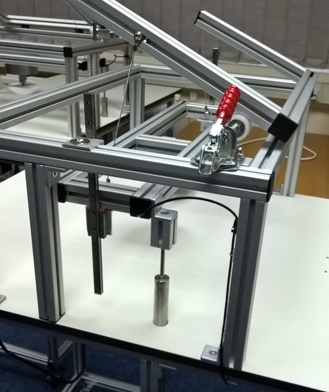
Universal Fabric Tension Tester for All Fabrics and Styles
The Challenge - Accurately Measure Fabric Tension on Any Style of Furniture. Fabric strength testing guarantees the fabric being used on furniture meets the high quality needed for durability, comfort and support. Choosing the wrong type of fabric can lead to fabric tearing, loss of customer satisfaction and a decrease in sales and profit. Find out how our miniature s-beam load cell, intuitive4-L digital indicator and industrial LVDT displacement sensors were used to determine fabric strength.

