At a Glance
- Stroke Ranges: ±0.5mm to ±500mm
- AC mV/V or DC Voltage / Current Output
- Environmental Protection: IP55
- Core-Only, Core + Extension,
- Spring-Loaded & Rod-End Bearing Versions
- Wide Range of Mechanical Configurations to Suit Your Specific Application
- Fast and Simple Installation – With our wide variety of packaging formats.
- Long Operating Life – No physical contact between the core and the coils.
- Ideally Suited for OEM Applications
- Let us do the Hard Work for You – We can provide you a wide range of supporting instrumentation.
Description
Applied Measurements AML/E series of standard LVDT displacement transducers are available with measuring ranges from ±0.5mm (0-1mm) up to ±500mm (0-1000mm).
Constructed from stainless steel, they are sealed to IP54 and can be supplied in a variety of mechanical configurations including plain core-only, plain core & extension rod, guided core & extension rod, spring-loaded core & extension rod with ball-end or with guided core & spherical rod-end bearings.
An AC mV/V output is available as standard, with a range of DC voltage signal output options also offered including 0-5Vdc, 0-10Vdc and ±2.5Vdc, as well as a 3-wire 4-20mA current output.
The broad range of typical applications for the AML/E series include Industrial Automation, R&D, Manufacturing and Machine Building.
Please see our full range of LVDT displacement transducers and position sensors.
Technical Specifications
| CHARACTERISTICS | AML/E | AML/EJ | AML/EU | AML/EU10 | AML/EI | AML/ED | UNITS |
|---|---|---|---|---|---|---|---|
| Stroke Measurement Range: | ±0.5, ±2.5, ±5, ±10, ±12.5, ±15, ±25, ±50, ±75, ±100, ±125, ±150, ±175, ±200, ±250 ±300, ±400, ±500, ±550 (maximum stroke is ±125 for Sprung Loaded Core & Extension - Option S) | millimetres | |||||
| Signal Output: | See Table Below | 0-5volt | 0-10volt | 4-20mA | ±2.5volt | ||
| No. of Wires | 6 | 4 | 3 | 3 | 3 | 4 | |
| Supply Voltage (unregulated): | 2 to 5Vrms @ 1 to 5kHz | 10-24Vdc | 14-24Vdc | 14-24Vdc | 12Vdc regulated | ||
| Supply Current: | - | 35mA @ 15V | 35mA @ 15V | 35mA typ. | 35mA @ 12V | ||
| Max. Loop Resistance: | - | - | - | 300 @ 30V | - | ohms | |
| Max. Output Sink Current: | - | 0.5 | 1 | - | 0.1 | milliamps | |
| Non-Linearity: | <0.50 | ±% Stroke Range | |||||
| Repeatability: | <0.10 | ±% Stroke Range | |||||
| Output Bandwidth: | 100 | 100 | 100 | 100 | 100 | 100 | Hz |
| Output Ripple: | - | 30mV max. | 30mV max. | 0.1% @ 20mA | 30mV max. | ||
| Operating Temperature Range: | AML/E & EJ: -30 to +85 Standard / -30 to +150 and -30 to +200 Optional -20 to +85 on DC/DC models / 0 to +70 for in-line conditioner (where fitted) | °C | |||||
| Zero Temperature Coefficient: | <0.020 | <0.010 | ±%Stroke Range/°C | ||||
| Span Temperature Coefficient: | <0.020 | <0.030 | ±%Stroke Range/°C | ||||
| Vibration Resistance: | 20g up to 2kHz | ||||||
| Shock Resistance: | 1000g for 10milliseconds | ||||||
| Construction Materials: | Body & Extension Rod: 303 St/Steel, Core: 416 St/Steel, Cable Gland: Nickel-Plated Brass, Spring: 316 St/Steel, Rod-End Bearings: Mild Steel | ||||||
| Electrical Connection: | 2 metre screened PVC cable* (*High-Temp Version = PTFE). Axial or radial exit available - see ordering codes for full details. | ||||||
| Environmental Sealing: | IP55 | ||||||
| Note: On DC output version (0Vdc / 4mA) is given with the core in the extended / outwards position. This can be reversed if required, please request Option Y on your order. |
|||||||
Product Dimensions
| Standard (Plain Core) | Option X&G (Core + Extension) | Option R (Rod End Bearings) | Standard, X&G, R | |||||||
|---|---|---|---|---|---|---|---|---|---|---|
| Stroke (mm) | Body Length (mm) | Core Length (mm) | Null Position (mm) | Body Length (mm) | Body Length (mm) | "L" (mm) | Sensitivity @ 3kHz with 50K Load (mV/V FRO) | Null (mV) | Primary Resistance (ohms) | Secondary Resistance (mm) |
| ±0.5 | 40 | 14 | 12.3 | 40 | 65 | 133 | 175 | 20 | 40 | 1800 |
| ±2.5 | 42 | 14 | 15.8 | 42 | 70 | 138 | 140 | 5 | 130 | 740 |
| ±5 | 83 | 29 | 30 | 83 | 95 | 163 | 135 | 5 | 48 | 108 |
| ±10 | 83 | 35 | 37 | 83 | 110 | 178 | 270 | 5 | 70 | 170 |
| ±12.5 | 102 | 35 | 44 | 102 | 117 | 185 | 195 | 5 | 120 | 190 |
| ±15 | 130 | 50 | 58 | 130 | 140 | 208 | 246 | 5 | 90 | 190 |
| ±25 | 170 | 76 | 79 | 170 | 185 | 253 | 225 | 5 | 130 | 210 |
| ±50 | 256 | 115 | 121 | 256 | 273 | 341 | 260 | 5 | 200 | 270 |
| ±75 | 330 | 138 | 156 | 330 | 345 | 413 | 390 | 20 | 260 | 460 |
| ±100 | 387 | 140 | 180 | 387 | 397 | 465 | 240 | 5 | 150 | 150 |
| ±125 | 445 | 152 | 208 | 445 | 455 | 523 | 260 | 5 | 180 | 320 |
| ±150 | 522 | 165 | 250 | 522 | 532 | 600 | 230 | 5 | 210 | 290 |
| ±175 | 573 | 160 | 264 | 573 | 583 | 651 | 260 | 2 | 230 | 360 |
| ±200 | 638 | 185 | 306 | 638 | 648 | 716 | 285 | 10 | 250 | 430 |
| ±250 | 760 | 170 | 348 | 760 | 770 | 838 | 310 | 10 | 290 | 560 |
| ±300 | 860 | 185 | 404 | 860 | 870 | 938 | 270 | 5 | 690 | 770 |
| ±400 | 1110 | 250 | 544 | 1110 | 1120 | 1188 | 440 | 20 | 450 | 1010 |
| ±500 | 1360 | 314 | 670 | 1360 | 1370 | 1438 | 475 | 10 | 550 | 1530 |
| ±550 | 1360 | 190 | 670 | 1360 | 1370 | 1438 | 345 | 10 | 550 | 1530 |
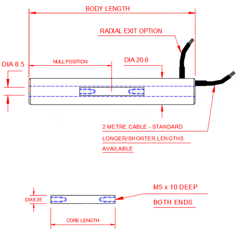
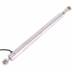
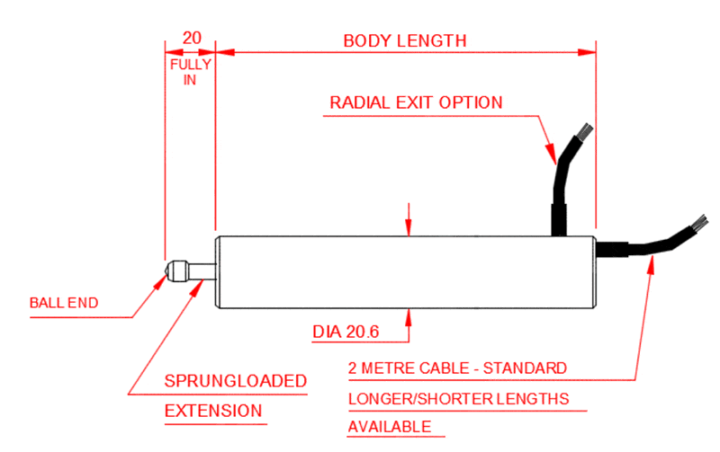
AML-E Standard LVDT Displacement Transducer AC Version Plain Core Outline 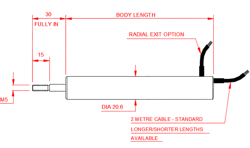
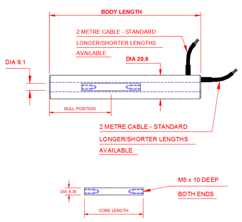
AML-E Standard LVDT Displacement Transducer AC Version Core + Extension (X&G) Outline 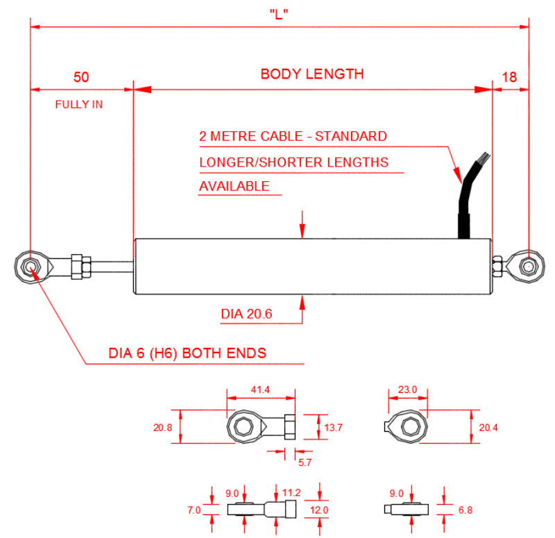
AML-E Standard LVDT Displacement Transducer AC Version Rod End Bearings (R) Outline
Plain Core AML-E Standard AC Version Options: A = axial cable exit; C = radial cable exit; J = 4-wire device; H = high temperature 150°C with PTFE cable; VH = very high temperature 200°C with PTFE cable.
Option X & G AML-E AC Version with Core + Extension Options: A = axial cable exit; C = radial cable exit; J = 4-wire device; X = extension with plain core; G = guided core & extension; H = high temperature 150°C with PTFE cable; VH = very high temperature 200°C with PTFE cable.
Option R AML-E AC Version with M6 Rod End Bearings Options: R = radial cable ONLY; J = 4-wire device; X = extension with plain core; G = guided core & extension; H = high temperature 150°C with PTFE cable; VH = very high temperature 200°C with PTFE cable; HR = high temperature 150°C with PTFE cable stainless steel rod end bearings.
Axial cable exit is NOT available with rod ends unless rod end is on the extension only.
| Stroke (mm) | Body Length (mm) | Sensitivity @ 3kHz with 50K Load (mV/V FRO) | Null (mV) | Primary Resistance (ohms) | Secondary Resistance (ohms) | Spring Rate (N/mm) |
|---|---|---|---|---|---|---|
| ±0.5 | 60 | 160 | 20 | 40 | 1800 | 0.3886 |
| ±2.5 | 67 | 165 | 5 | 130 | 740 | 0.2914 |
| ±5 | 108 | 130 | 5 | 48 | 108 | 0.1166 |
| ±10 | 108 | 146 | 5 | 70 | 170 | 0.1166 |
| ±12.5 | 127 | 185 | 5 | 120 | 190 | 0.0897 |
| ±15 | 155 | 220 | 5 | 90 | 190 | 0.0729 |
| ±25 | 195 | 206 | 5 | 130 | 210 | 0.0555 |
| ±50 | 281 | 182 | 5 | 200 | 270 | 0.0389 |
| ±75 | 355 | 260 | 20 | 260 | 460 | 0.0291 |
| ±100 | 355 | 350 | 20 | 260 | 460 | 0.0291 |
| ±125 | 412 | 178 | 5 | 145 | 230 | 0.0253 |
AML-E Standard LVDT Displacement Transducer AC Version Sprung-Loaded (S) Outline
Option S AML-E AC Version Sprung Loaded Options: A = axial cable exit; C = radial cable exit; H = High Temperature 150°C, J = 4-wire device; K = extension rod wiper.
VH high-temperature 200°C options are NOT available on sprung loaded.
| Standard | Option X&G | Option R | Option S | |||||
|---|---|---|---|---|---|---|---|---|
| Stroke (mm) | Body Length (mm) | Core Length (mm) | Null Position (mm) | Body Length (mm) | Body Length (mm) | "L" (mm) | Body Length (mm) | Spring Rate (N/mm) |
| ±0.5 | 82 | 14 | 12.3 | 82 | 92 | 160 | 100 | 0.4318 |
| ±2.5 | 85 | 14 | 15.8 | 85 | 100 | 168 | 107 | 0.2914 |
| ±5 | 123 | 29 | 30 | 123 | 133 | 201 | 148 | 0.1295 |
| ±10 | 130 | 35 | 37 | 130 | 143 | 211 | 148 | 0.1295 |
| ±12.5 | 142 | 35 | 44 | 142 | 152 | 220 | 167 | 0.0933 |
| ±15 | 170 | 50 | 58 | 170 | 180 | 248 | 195 | 0.0833 |
| ±25 | 210 | 76 | 79 | 210 | 220 | 288 | 235 | 0.0583 |
| ±50 | 296 | 115 | 121 | 296 | 306 | 374 | 321 | 0.0376 |
| ±75 | 370 | 138 | 156 | 370 | 380 | 448 | 395 | 0.0291 |
| ±100 | 427 | 140 | 180 | 427 | 437 | 505 | 395 | 0.0291 |
| ±125 | 485 | 152 | 208 | 485 | 495 | 563 | 470 | 0.0253 |
| ±150 | 562 | 165 | 250 | 562 | 572 | 640 | n/a | n/a |
| ±175 | 613 | 160 | 264 | 613 | 623 | 691 | n/a | n/a |
| ±200 | 678 | 185 | 306 | 678 | 688 | 756 | n/a | n/a |
| ±250 | 800 | 170 | 348 | 800 | 810 | 878 | n/a | n/a |
| ±300 | 900 | 185 | 404 | 900 | 910 | 978 | n/a | n/a |
| ±400 | 1150 | 250 | 544 | 1150 | 1160 | 1228 | n/a | n/a |
| ±500 | 1400 | 314 | 670 | 1400 | 1410 | 1478 | n/a | n/a |
| ±550 | 1400 | 190 | 670 | 1400 | 1410 | 1478 | n/a | n/a |
AML-E Standard LVDT Displacement Transducer DC Version Plain Core Outline 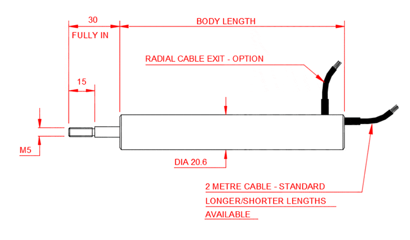
AML-E Standard LVDT Displacement Transducer DC Version Core + Extension (X&G) Outline 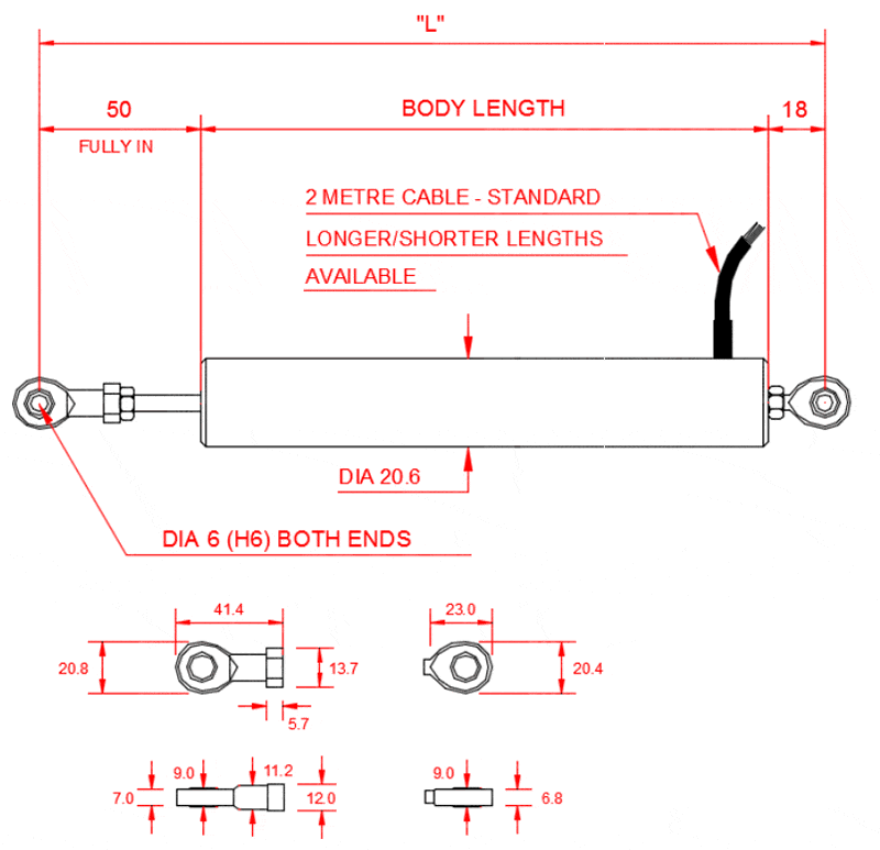
AML-E Standard LVDT Displacement Transducer DC Version with M6 Rod End Bearings (R) Outline 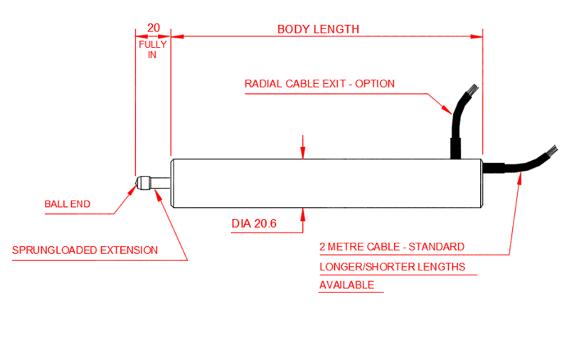
AML-E Standard LVDT Displacement Transducer DC Version Sprung-Loaded (S) Outline
Plain Core AML-E Standard DC Version Options: A = axial cable exit; C = radial cable exit; I = 4-20mA output; U = 0-5V output; U-10 = 0-10V output; D = DC bipolar output; Y = reverse output (eg. 4mA fully in instead of default 20mA).
H and VH high-temperature options are not available.
Option X & G AML-E Standard DC Version with Core & Extension Options: A = axial cable exit; C = radial cable exit; G = guided core & extension; I = 4-20mA output; U = 0-5V output; U-10 = 0-10V output; D = DC bipolar output; Y = reverse output (eg. 4mA fully in instead of default 20mA).
H and VH high-temperature options are not available.
Option R AML-E Standard DC Version with M6 Rod End Bearings Options: C = radial cable exit; I = 4-20mA output; U = 0-5V output; U-10 = 0-10V output; D = DC bipolar output; Y = reverse output (eg. 4mA fully in instead of default 20mA).
H and VH high-temperature options are not available.
Option S AML-E Standard DC Version Sprung Loaded Options: A = axial cable exit; C = radial cable exit; K = extension rod wiper; I = 4-20mA output; U = 0-5V output; U-10 = 0-10V output; D = DC bipolar output; Y = reverse output (eg. 4mA fully in instead of default 20mA).
H and VH high-temperature options are not available.
Ordering Codes & Options
| AML/EU10+/-500mm-X0A-02-000 (example code) | AML/E | U10 | +/-500mm | - | X | O | A | - | 02 | - | 000 |
|---|---|---|---|---|---|---|---|---|---|---|---|
| Product Family | |||||||||||
| AML/E | AML/E | ||||||||||
| Electrical Output | |||||||||||
| Blank = 6-wire AC mV/V | Blank | ||||||||||
| J = 4-wire AC mV/V | J | ||||||||||
| U = 0-5Vdc | U | ||||||||||
| U10 = 0-10Vdc | U10 | ||||||||||
| I = 4-20mA | I | ||||||||||
| D = ±2.5Vdc (12Vdc regulated supply required) | D | ||||||||||
| Stroke Range | |||||||||||
| +/-0.5mm (0-1mm) | +/-0.5mm | ||||||||||
| +/-2.5mm (0-5mm) | +/-2.5mm | ||||||||||
| +/-5mm (0-10mm) | +/-5mm | ||||||||||
| +/-10mm (0-20mm) | +/-10mm | ||||||||||
| +/-12.5mm | +/-12.5mm | ||||||||||
| +/-15mm (0-30mm) | +/-15mm | ||||||||||
| +/-25mm (0-50mm) | +/-25mm | ||||||||||
| +/-50mm (0-100mm) | +/-50mm | ||||||||||
| +/-75mm (0-150mm) | +/-75mm | ||||||||||
| +/-100mm (0-200mm) | +/-100mm | ||||||||||
| +/-125mm (0-250mm) | +/-125mm | ||||||||||
| +/-150mm (0-300mm) | +/-150mm | ||||||||||
| +/-175mm (0-350mm) | +/-175mm | ||||||||||
| +/-200mm (0-400mm) | +/-200mm | ||||||||||
| +/-250mm (0-500mm) | +/-250mm | ||||||||||
| +/-300mm (0-600mm) | +/-300mm | ||||||||||
| +/-400mm (0-800mm) | +/-400mm | ||||||||||
| +/-500mm (0-1000mm) | +/-500mm | ||||||||||
| +/-550mm (0-1100mm) | +/-550mm | ||||||||||
| Mechanical Configuration | |||||||||||
| C = Core Only | - | C | |||||||||
| X = Un-Guided Core & Extension Rod | - | X | |||||||||
| G = Guided Core & Extension Rod | - | G | |||||||||
| S = Spring Loaded Core & Extension Rod with Ball-Tip (±125mm max range) | - | S | |||||||||
| R = Rod-End Bearings - Mild Steel (with Guided Core) | - | R | |||||||||
| H = 150ºC High Temperature Version AC only Core Only (DC output requires in-line amplifier @ 70°C max) | - | H | |||||||||
| HR = 150ºC High Temperature Version with Stainless Steel RodEnd Bearings | - | HR | |||||||||
| VH = 200ºC Very High Temperature, Core Only (AC output only) | - | VH | |||||||||
| VHR = 200ºC Very High Temperature + Stainless Steel Rod End Bearings with Guided Core (AC output only) | - | VHR | |||||||||
| HG = 150ºC High Temperature Version Guided Core & Extension Rod (DC output requires in-line amplifier @ 70°C max) | - | HG | |||||||||
| HS = 150ºC High Temperature Version Spring Loaded Core & Extension Rod with Ball-Tip (±125mm max range) (DC output requires in-line amplifier @ 70°C max) | - | HS | |||||||||
| HX = 150ºC High Temperature Version Un-Guided Core & Extension Rod (DC output requires in-line amplifier @ 70°C max) | - | HX | |||||||||
| VHX = 200ºC Very High Temperature, with PTFE cable, Unguided Core + Extension Rod (AC output only) | - | VHX | |||||||||
| VHG = 200ºC Very High Temperature, with PTFE cable, Guided Core + Extension Rod (AC output only) | - | VHG | |||||||||
| Output Direction (only affects DC output versions) | |||||||||||
| 0 = Zero with core extended, Full Scale with core retracted | 0 | ||||||||||
| Y = Full Scale with core extended, Zero with core retracted | Y | ||||||||||
| Cable Exit Direction | |||||||||||
| A = Axial (not available on rod end bearing version) | A | ||||||||||
| R = Radial | R | ||||||||||
| Cable Length (in metres) | |||||||||||
| 02 = 2 metres (standard) | - | 02 | |||||||||
| 0,2 = 0.2 metres | - | 0,2 | |||||||||
| 10 = 10 metres | - | 10 | |||||||||
| Specials Code | |||||||||||
| 000 = No Special Requirements | - | 000 | |||||||||
| Sales To Provide Specials Codes As Required |
Related Products
 LVDT In-Line Amplifier | LVDT-810xFrom £173
 Portable Desktop Enclosure | Panel Meter Enclosure | PCCFits ALL Intuitive2 & Intuitive4 IndicatorsFrom £266
 Universal Process Input Digital Indicator | Intuitive4-PHighly configurable, modular constructionFrom £252Buy Online
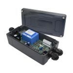 LVDT Signal Conditioner | LVDT AmplifierDISCONTINUED PRODUCT