At a Glance
- Engineering Unit Conversion
- TEDS Templates 33, 40, 41
- Sensitivities up to +/-480mV/V
- Environmental Protection: IP64
- PC-based Data Logging via Toolkit
- 2x AA Batteries or USB Powered
- Measurement rate up to 2,400 SPS
- Works with all Strain Gauge Bridge Transducers
- Two Calibration Channels
- TEDS Enabled
- Enhanced Calibration Options
- Works with 4-wire and 6-wire sensors
- 128 x 64 dot matrix display with backlight
- Configuration Toolkit Software (Windows only)
Description
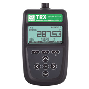
The new TEDS enabled portable strain gauge sensor display TRX by Applied Measurements is a microprocessor-based portable display for all types of strain gauge bridge sensors with an output sensitivity from 0.5mV/V right up to 480mV/V. It is a direct replacement for the TR150 handheld display, with additional channels and features.
The display can be used as a handheld device (like the TR150) and also comes with optional mounting accessories for desks, walls and magnetic equipment.
The basic version offers 2 calibration channels/ranges, allowing optimised calibration of bi-directional transducers to give the best possible accuracy in tension and compression (or clockwise and counter-clockwise in the case of torque transducers. Each channel also offers enhanced calibration options in the form of either a linearised calibration or a polynomial calibration to give even greater accuracy from your strain gauge-based transducer. Plus, it supports TEDS templates 33 (bridge sensors template), 40 (multiple data pairs), and 41 (calibration curve polynomial).
Once calibrated in your preferred engineering units, you can switch freely between various other engineering units according to your sensor type at the press of a button; i.e bar to psi (pressure), kg to Newtons (force), Nm to lb-ft (torque), and so on.
The free downloadable toolkit software enables advanced calibration and configuration options as well as data logging via the free Toolkit software, while simple configuration and 2-point calibration can be easily done/completed using the front panel buttons.
Functions on the TRX include:
- Switching Between Engineering Units
- Range Selection
- Display Hold/Freeze
- Gross/Net indication selection
- Peak Hold selection
- Trough Hold selection
- TEDS support
TEDS Functionality
TEDS delivers a simple ‘plug and play’ technology. You simply connect a TEDS integrated sensor into the TRX and the information stored on the integrated TEDS chip transfers the critical calibration information to and from the connected TEDS devices.
TEDS equipment is interchangeable without having to recalibrate the devices. The TRX strain gauge display will remember the last 20 TEDS devices that have been connected to it.
The TEDS information that can be read by the TRX consists of the TEDS bridge sensors transducer template 33 which includes the sensor manufacturer, model, and serial numbers, the calibration template table 40 (maximum calibration points of 10) and the calibration curve template 41 (up to a maximum number of segments of 1 and a maximum number of coefficients = 10).
The TRX strain gauge display also gives the user the option to ignore the TEDS data and use the TRX calibration ranges instead.
The Display
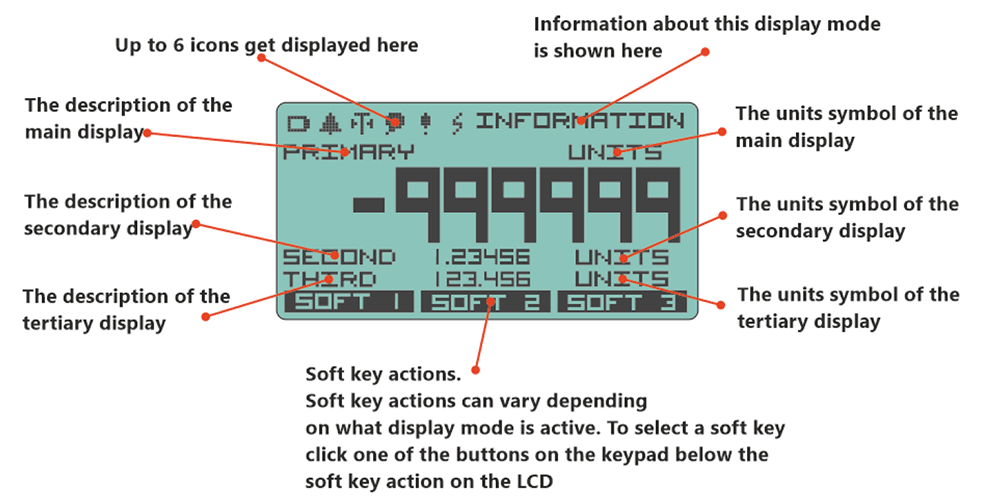
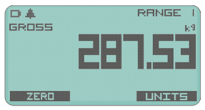
128 x 64 monochrome dot matrix display with backlight. The display will change depending on the mode and options you have enabled. Below are some examples of a 3 value display and a simple display.


Don’t hesitate to get in touch with your Applied Measurements expert sales team using the form in the sidebar, or call +44 (0) 1189 817339, or send an email to [email protected] and Applied Measurements will be happy to assist you with your enquiry.
Technical Specifications
| CHARACTERISTICS | Min | Typical | Max | Units |
|---|---|---|---|---|
| Strain Gauge Measurement | 6-wire | Can also accept a 4-wire input. | ||
| Display | 128 x 64 dot matrix display with backlight | |||
| Resolution at 1 SPS | 1,100,000 (20) | Counts (bit) | ||
| Resolution at 10 SPS | 550,000 (19) | Counts (bit) Noise-free at ±7.5 mV/V range | ||
| Resolution at 2,400 SPS | 6,500 (14.3) | Counts (bit) | ||
| Linearity | ±2 | ppm/FSR In high-quality operating mode (Linearity error can be further reduced by device linearization calibration) |
||
| Excitation | 3.2 | 3.3 | 3.4 | Vdc |
| Drive Capability | 85 | - | 10,000 | Ohm |
| Sensitivity | ±7.5 | - | ±480 | mV/V (Effective sensitivity from ±0.5mV/V with reduced resolution) |
| Offset Temperature Stability | 12 | nV/°C At 2.5 mV/V | ||
| Gain Temperature Stability | 1 | 2 | ppm/°C | |
| Internal Resolution | 24 | bit | ||
| Display Resolution | 128 x 64 | Pixels | ||
| Buzzer Acoustic Output | 45 | dB | ||
| Power Supply | 2x 1.5V AA (LR6) batteries or USB powered | Operation with batteries rated below 1.5V is not guaranteed to provide specified performance. | ||
| Power Consumption | 35 | mA (in normal measurement mode) | ||
| Standby Current | 75 | μA | ||
| Battery Life Low Quality 1Hz | 220 | Hrs | ||
| Battery Life High Quality 1,200Hz | 60 | Hrs | ||
| Operating Temperature Range | -10 | +50 | °C | |
| Storage Temperature Range | -20 | +80 | °C | |
| Operating Humidity Range | 0 | 95 | %RH | |
| Environmental Protection | IP64 (With connector mated or unmated) | |||
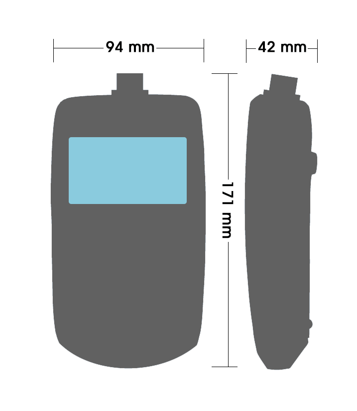
| External Dimensions | L: 170 mm, W: 94 mm, H: 42 mm (excluding mated connector) | |||
| Weight | 365 | g including batteries | ||
Product Dimensions

Ordering Codes & Options
| Core Product | Details | Example Result |
|---|---|---|
| TRX Portable Strain Gauge Display | Standard Version with 2 Calibration Ranges | TRX-A |

