
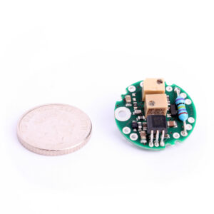
At a Glance
- Ø19.5mm x 7.6mm high
- 0-5Vdc, 0-10Vdc, 4-20mA, & ±10Vdc Output Versions
- Low Current Consumption
- Bandwidth: 1kHz max.
- Available with In-Line enclosure for mounting on transducer cable
- Ideal for when you want a Small Amplifier to Fit Inside Your Load Cell
- Compact at Only 19mm Diameter
- Can Fit Inside a Wide Variety of Strain Gauge Transducers
- 6 Different Outputs to Suit Your Exact Application
Description
The ICA miniature load cell amplifier measures just 19mm in diameter and 7.6mm in height and is designed for incorporation into the body of a broad range of strain gauge transducers and load cells.
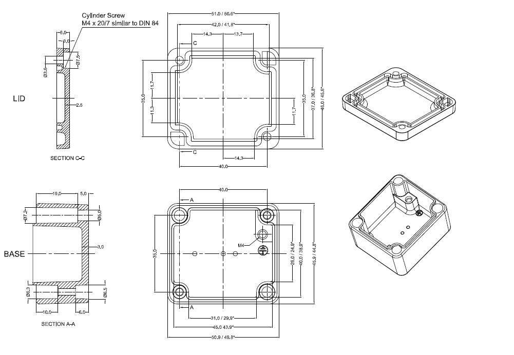
When space inside the load cell or transducer is restricted, the ICA miniature load cell amplifier can also be mounted in-line on the transducer cable inside a dedicated enclosure suitable for the application environment. We offer our own compact IP65-rated die cast enclosure the measures just 50mm x 45mm x 30mm which suits most general industrial applications (pictured right).
There are a total of six output variants of the miniature ICA load cell amplifier available:
- ICA1H: 3 wire – 0.1 to 10.1Vdc (13 to 28Vdc supply)
- ICA2H: 3 wire – 0.1 to 5.1Vdc (8.5 to 28Vdc supply)
- ICA3H: 4 wire – (±10Vdc/±15Vdc supply)
- ICA4H: 3 wire – 4-20mA (13 to 28Vdc supply)
- ICA5S: 2 wire – 4-20mA (7.5 to 28Vdc supply)
- ICA6H: 3 wire – (±10Vdc/14-27Vdc supply)
We hold stock of all the miniature load cell amplifier models mentioned above for immediate despatch.
Technical Specifications
| ELECTRICAL & ENVIRONMENTAL | ||||||||
|---|---|---|---|---|---|---|---|---|
| Characteristics | ICA1H | ICA2H | ICA3H | ICA4H | ICA5S | ICA6H | Units | |
| Output Range: | 0.1 to 10.1 Vdc | 0.1 to 5.1 Vdc | 0 to ±10Vdc | 4 to 20mA | 4 to 20mA | 0 to ±10Vdc | See opposite | |
| Supply Voltage Range | 13 to 28 (24 typical) | 8.5 to 28 (12 typical) | ±13 to ±15 (±14 typical) | 13 to 28 (24 typical) | 7.5 to 28 (24 typical) | 14 to 27 (15 typical) see note 7 | volts | |
| Operating Current | 9 to 22 (13 typical) | 9 to 22 (13 typical) | 9 to 22 (13 typical) | 9 to 22 (13 typical) | 9 to 20 (13 typical) | 9 to 22 (13 typical) | mA | |
| Operating Temperature Range | -40 to +85 | -40 to +85 | -40 to +85 | -40 to +85 | -40 to +85 | -40 to +85 | °C | |
| Storage Temperature Range | -40 to +85 | -40 to +85 | -40 to +85 | -40 to +85 | -40 to +85 | -40 to +85 | °C | |
| Reverse Polarity Protection (minimum) | -30 | -30 | -30 | -30 | -30 | -30 | volts | |
| MEASUREMENT | ||||||||
| Bridge Excitation | 5.00 ±0.1 | 5.00 ±0.1 | 5.00 ±0.1 | 5.00 ±0.1 | 1.11 ±0.05 | 5.00 ±0.1 | volts DC | |
| Bridge Impedance | 350 to 5000 (1000 typical) | 350 to 5000 (1000 typical) | 350 to 5000 (1000 typical) | 350 to 5000 (1000 typical) | 350 to 5000 (1000 typical) | 350 to 5000 (1000 typical) | ohms | |
| Bridge Sensitivity | 0.5 to 50 (2.5 typical) see note 1a | 0.5 to 50 (2.5 typical) see note 1a | 0.5 to 50 (2.5 typical) see note 1a | 0.5 to 150 (2.5 typical) see note 1a | 0.5 to 55 (2.5 typical) see note 4 | 0.5 to 150 (2.5 typical) see note 1b | mV/V | |
| Output Load | >5000 | >5000 | >5000 | <900 see note 2 | <800 see note 2 | >5000 | ohms | |
| Bandwidth | DC to 1000 | DC to 1000 | DC to 1000 | DC to 1000 | DC to 1000 | DC to 1000 | Hz | |
| Zero Adjustment (typical) | ±2 | ±2 | ±2 | ±2 | ±2 (See note 6) | ±2 | %Full Range (10V), (16mA in the case for ICA5S) | |
| Span Adjustment (typical) | ±8 | ±8 | ±8 | ±8 | ±8 | ±8 | %Full Range (10V), (16mA in the case for ICA5S) | |
| Linearity (typical) | 0.02 | 0.02 | 0.02 | 0.02 | 0.02 | 0.02 | %Full Range (10V), (16mA in the case for ICA5S) | |
| Temperature Stability | ||||||||
| Zero Temperature Stability (at 2.5mV/V) | 0.0004 to 0.0015 | 0.0004 to 0.0015 | 0.0004 to 0.0015 | 0.0004 to 0.0015 | 0.001 to 0.005 | 0.0004 to 0.0015 | ±%FR/°C | |
| Span Temperature Stability (at 2.5mV/V) | 0.002 to 0.0051 | 0.002 to 0.0051 | 0.002 to 0.0051 | 0.002 to 0.0051 | 0.007 to 0.014 | 0.002 to 0.0051 | ±%FR/°C | |
Note 1a: Set by calibration resistor. The voltage between either of the power supply connections and the load cell shield should not exceed 50 V. Any leakage will be greater than 10 M ohms.
Note 1b: Set by calibration resistor.
Note 2: 24 V minimum supply/sink mode – includes loop wiring resistance.
Note 3: 1000 ohm load cell – Typically 0.55 V for 350 ohm cell.
Note 4: Set by calibration resistor. Load cells with less than 1 mV/V sensitivity are not recommended – drift and noise performance will suffer.
Note 5: 1000 ohms load cell – change R(offset) to suit other load cell impedances.
Note 6: Recommended bridge impedance is 1,000 ohms.
Note 7: Ideally this should be limited to +15 V to +18 V for 350 ohm load cells to minimise the on-board temperature rise thereby reducing any warm-up time.
Product Dimensions

Ordering Codes & Options
| Core Product | Supply Voltage | Example Result |
|---|---|---|
| ICA | 0.1 to 10.1Vdc / 13 to 28Vdc | ICA1H |
| ICA | 0.1 to 5.1Vdc / 8.5 to 28Vdc | ICA2H |
| ICA | 0 to ±10Vdc / ±13 to ±15Vdc | ICA3H |
| ICA | 4 to 20mA (3-wire) / 13 to 28Vdc | ICA4H |
| ICA | 4 to 20mA (2-wire) / 7.5 to 28Vdc | ICA5S |
| ICA | 0 to ±10Vdc / 14 to 27Vdc (See note 9) | ICA6H |
Case Studies
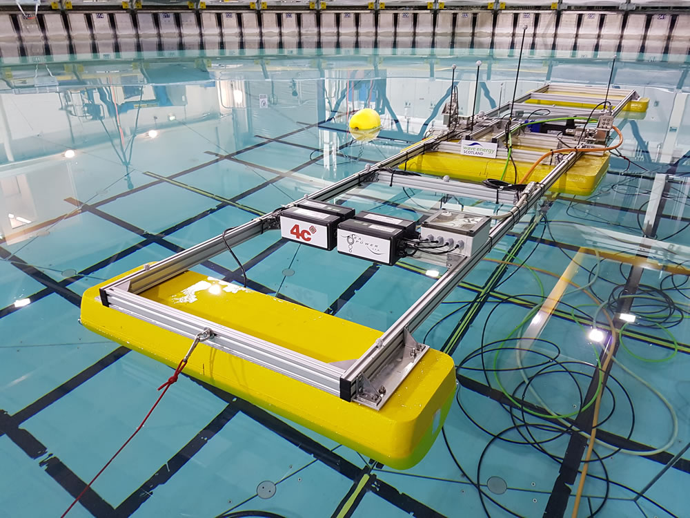
Real Life: Power Take-Off Torque Monitoring – Accurate, Fast and Simple!
Read the real life case study of power take-off torque monitoring on the Wave Energy Converter The SeaPower Platform. See how our complete torque measuring system enabled engineers to accurately monitor the torque applied by the Wave Energy Converter as it responded to waves in the test tank with accurate, fast and reliable results.
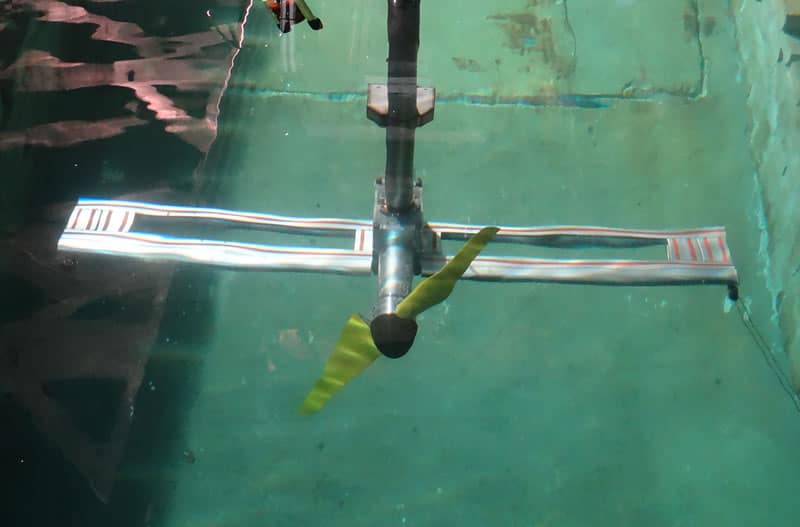
Submersible Load Cells Lower the Cost of Large Tidal Turbine Designs
This case study aims to significantly reduce the cost of large scale tidal turbine designs using our submersible load cells. The tidal turbine test rig was placed in a state-of-the-art test tank, where the team were able to increasing the size, flow rate and turbulence levels within the tank. Lowering the cost of rotor blade manufacture would make this renewable energy more economical to use and widely accessible, benefiting not only the UK renewable tidal energy markets but developing tidal energy countries too. Our submersible load cells measured both the torque and the thrust of the underwater tidal turbine design.
Our Shear Pin Load Cells and Draw Wire Sensors Deliver Flawless Results in Sub-Zero Temperatures
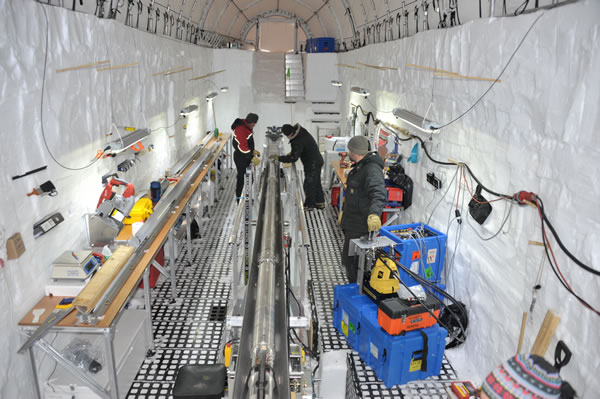
Applied Measurements were contacted by Victoria University of Wellington to provide reliable and accurate equipment that could operate in the sub-zero temperatures of the Antarctic. Using Applied Measurements’ two customised DBEP shear pin load cells, a WS12 draw wire sensor and four intuitive2 displays, the RICE team were able to successfully extract a 763m deep ice core from an ice cap on Roosevelt Island.
Applied Measurements’ Submersible Load Cells fitted to the World’s Largest All-Terrain Hexapod
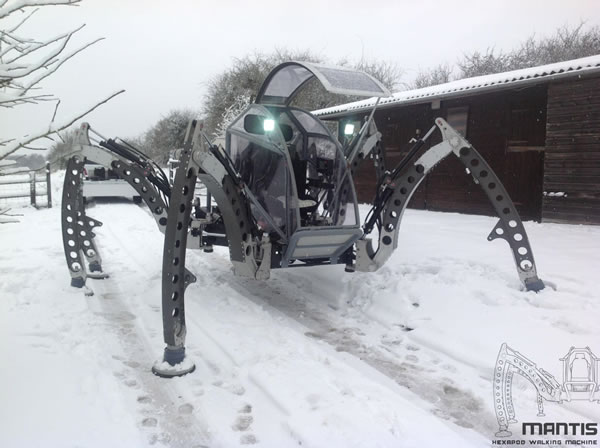
Applied Measurements provided the load cells needed to monitor the force on individual legs to stop the Mantis (the world’s largest hydraulic hexapod robot) walking into a situation that is hazardous to its overall stability. Assisted by Applied Measurements’ compact and submersible DSCC load cells, the Mantis successfully travels over all slopes and uneven surfaces, traversing most types of terrain, even wading through water.
Load Pins and Position Sensors used for Antarctic Research
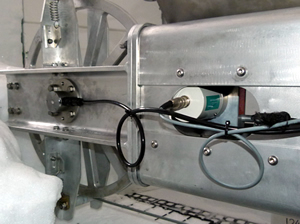
Applied Measurements needed to design and manufacture a pair of custom load pins for the university that could compensate for temperatures as low as -30degC. The load pin also had a built in ICA4S amplifier that could give a 4-20mA output for them to use to monitor the drilling forces.
Related Products
 Strain Gauge Displacement Sensor | Linear Position Sensor | AML/SGD0-5mm to 0-100mmFrom £429Buy Online
 Torque Transducers & Torque Sensors
 Load Cells & Force Sensors